Virtual-Engineering Best Practices
May 1, 2018Comments
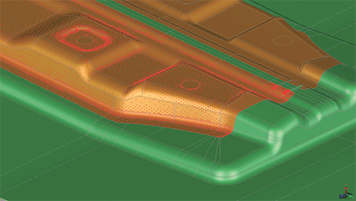 |
| This simulation graphic shows a springback vector field overlaid onto die surfaces in preparation for springback compensation. |
Springback best practices, diligently accumulated over decades, have been effective in managing dimensional compliance on mild steel and high-strength low-alloy stampings—even with little or no support from virtual engineering tools. Over the past dozen years, newer grades of advanced high strength steels and aluminum alloys, however, have upended this store of accepted best practices and collective wisdom. The role of virtual engineering in the mitigation and management of springback for these materials now is clearly acknowledged, but, best practices toward effective application of these tools are not widely and clearly understood.
With that sentiment, Kidambi Kannan, technical manager at AutoForm Engineering USA, Inc., provides a rundown of virtual-engineering best practices, noting that virtual-engineering tools have evolved to a high level of dependability, and that no physical detail is too trivial to model in the virtual world. Here Kannan presents an actionable list of virtual-engineering best practices that crystallize these themes, and which have helped practitioners achieve higher levels of success in mitigating and managing springback.
- Model die condition and simulate process in detail, and exactly as intended to build: binder spotting/bearing or gap; die clearances; bead shapes; panel-locating/positioning pilots and gauges; tool kinematics; tonnage; form-pad bearing; trim tools and timing; etc.
- Model material accurately using data from material tests; avoid generic and non-representative data.
- Respect and apply appropriate numerical-control settings to ensure the accurate modeling of tool surfaces and sheetmetal.
- Apply scaling to the draw die; morph trim-die surfaces to locate the draw panel without crushing; and validate locating in simulation and adjust it until satisfactory.
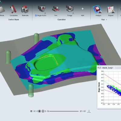
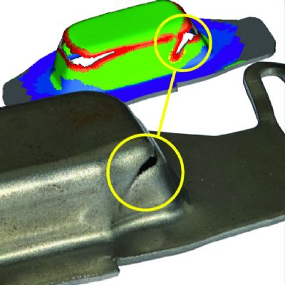
- Develop and finalize a full process, validated in simulation, to produce a panel fully acceptable on all required formability metrics. The panel should be safe relative to forming limit; should meet edge- and surface-failure criteria; exhibit acceptable thinning and thickening; contain no foldovers and no buckles on seal surfaces; and offer the highest level of stretch achievable, as uniformly distributed on the panel as possible.
- Finalize the developed blank outline and/or trim lines. After finalization, adjust the process as necessary to re-establish an acceptable panel.
- Measure springback in simulation, after each operation, with due diligence toward firm and repeatable panel positioning that avoids sprung-panel distortion. Understand the evolution of springback from one operation to next.
- Recognize, using virtual tools, the mode of observed springback. Twist and/or oil-canning, and panel-sidewall curl cannot be compensated for, but must be addressed through process changes, or even product modifications, which sets the virtual-engineering process all the way back to step one. Likewise, springback magnitudes greater than 10 mm are difficult to compensate for, requiring process/product adjustments. The sooner these potential issues are identified, the less expensive—in time and cost—it will be to mitigate these through appropriate countermeasures.
- Validate, using virtual tools, the robustness of the developed die and process to common uncontrollable parameters in production—material, gauge, blank gauging, lube, etc. Are formability and, more importantly, springback outcomes narrowly repeatable despite all of that production ‘noise?’ If not, the ‘compensatability’ of dies is severely compromised. The die and process will need to be improved, leading toward robust outcomes, before investing effort in compensation.
- Last but not least, build the dies and process exactly as they have been engineered and validated in simulation.
AutoForm Engineering USA, Inc.: www.autoform.com
View Glossary of Metalforming Terms
See also: Autoform Engineering USA
Technologies: Software