Preventing Press and Tooling Damage
After a mechanical-press slide reaches peak velocity—approximately 90 deg. of crank-shaft rotation—the slide begins to decelerate until it eventually reaches zero velocity at bottom-dead center. The slide immediately accelerates again in the opposite direction on the upstroke. Because the ram motion generates inertia—the greater the mass and speed, the greater the inertial forces—the ram wants to continue its downward path. These inertial forces place tremendous stress on press components, especially the pitman connections.
Depending on the magnitude of inertia forces and the rigidity of the press design, the pitman can elongate, effectively reducing shut height. This shut-height reduction causes die damage and introduces additional press stresses, affecting the large end of the pitman on the crank journal and causing additional frame deflections.
Slug breaking in high-speed-punching operations can generate significantly higher snapthrough loads, transferring additional impact energy into the frame structure in the form of vibrations. As press speeds increase there is less time to dissipate these vibrations, and they eventually can reach critical levels characterized by magnified stresses. This creates a range of nuisance problems, from nuts and bolts loosening to catastrophic problems such as crankshaft and tie-rod breakage.
One way to reduce reverse tonnage and associated vibrations: Stagger the punch lengths equivalent to the shear-band width in the holes previously punched. This reduces both impact and snapthrough loads. Staggering punches in this manner allows the next group of punches to contact the workpiece material prior to the first group snapping through. The snapthrough energy from the first group of punched holes drives the next set of punches through the part material.
High-speed stamping generates a significant amount of frictional heat and it decreases the amount of contact time the tooling has with the workpiece by the same factor. This reduces the opportunity for the punch to dissipate heat into the work material, which affords some additional cooling.
Because small punches have much less ability to dissipate heat, they are more prone to over-heat. This can result in a loss of hardness, reduced wear resistance and dimensional instability. High-speed or powdered-metal (PM) tool steels such as M4 and PM-10V, tempered at temperatures greater than 1000 deg. F, exhibit temper resistance superior to A2 and D2 in high-speed applications.
 Another tool-steel solution may involve cemented carbide. “Cemented” refers to the tungsten-carbide particles mixed with a metallic binder matrix and cemented together in a sintering process. The carbide industry commonly refers to this material as carbide, but uses the terms solid carbide, tungsten carbide and cemented carbide interchangeably.
Hardness is likely the most beneficial property of cemented carbide for metal-stamping processes. The physical property is most important when it comes to abrasion resistance.
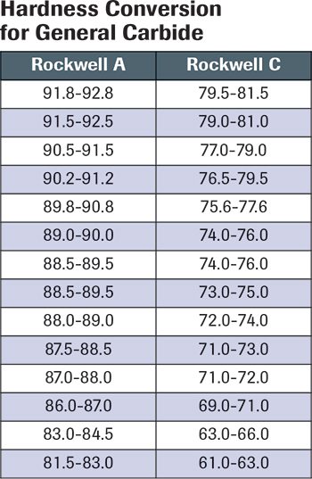
Hardness values for cemented carbide usually are expressed in terms of Rockwell A (HRA) or Vickers values. Traditional tool steels, measured in a similar fashion, are expressed in terms of Rockwell C (HRC).
The Hardness Conversion for General Carbine chart depicts the approximate conversion from HRA to HRC. Note that a traditional tool steel heattreated and tempered to 62 HRC remains relatively soft when compared to a 6-percent cobalt grade carbide with a harness value of 92 HRA.
Carbide tooling also requires special care and consideration during tool construction and maintenance.
Component failure can occur when using ram-type electrodes in electrical-discharge machining (EDM) if the electrical amperage power is too high. Thermal micro-fracturing or heat checks can occur, causing crack initiation, notch propagation and premature tool/part wear.
Fracturing or breaking of carbide tools also can occur when using a wire EDM. This damage usually occurs due to improper processing of the carbide material. Specifying EDM-quality material from the carbide manufacturer helps to avoid this.
Carbide-compatible coolants are required when grinding carbide to ensure proper cooling, lubrication and corrosion protection of the tool. Corrosion of cemented carbide, usually referred to as leaching, is the removal of cobalt from the matrix. Without the cobalt binder to hold the tungsten carbides in place, grain dislodgement occurs, expediting wear on the carbide edge or surface. The result is loss of dimensional stability, erosion of the cutting edge and tool surface, and, ultimately, premature tool failure.
Do you want to learn more about high-speed stamping processes? Then plan to attend PMA’s High-Speed Stamping seminar in Cleveland, OH, May 16-17. Visit www.pma.org to register or contact Marianne Sichi at msichi@pma.org for information. MF
Industry-Related Terms: Center,
Checks,
Die,
Edge,
Electrodes,
Form,
Grinding,
Ram,
Shut Height,
Surface,
TransferView Glossary of Metalforming Terms Technologies: Stamping Presses, Tooling


 Peter Ulintz

 Video
Video