


 Stuart Keeler
Cutting Can Spoil Stretchability
December 1, 2015Comments
A recent e-mail from a reader asked a very difficult question: “Forming-limit curves (FLCs) are used to warn when forming sheetmetal approaches failure,” he wrote. “Is there a comparable method to predict how much one can stretch a cut edge without initiating a tear? The FLC graphs do not work. This number is needed for our die and stamping designers.”
FLCs are available that show the maximum amount of strain allowed before a stamping necks and fails for a
s-received unworked sheetmetal. Circle grids etched into the surface of a stamping under evaluation allow measurement of the amount of strain the stamping already has accumulated at different locations. Plotting these strains on the FLC allows one to determine how close the stamping is to failure. However, this analysis does not work for the onset of edge cracking.

Fig. 1—Severe damage and n-value reduction can extend half-thickness or more from the cut edge.
When forming an edge created by blanking, cutting, trimming, punching, shearing or other separation process, one must consider a lengthy list of variables that can greatly impact edge stretchability.
1) Amount of cold work. Standard cutting with a shear can cause deformation in the workpiece material to extend one-half thickness (or even full sheet thickness) back into the sheet from the cut edge (Fig. 1). Any cold working or other deformation (red zone) causes a reduction in the work-hardening exponent (n-value). The maximum n-value reduction occurs at the edge of the cut where edge stretching requires the maximum stretchability to avoid early edge cracking.
2) Material microstructure. Not all material is free of additives within its structure. Some are intentionally added to increase material strength, by altering grain size, the amount of precipitates, replacing iron atoms with substitutional atoms, etc. These strengthening features reduce n-value. The worst unwanted additives are manganese-sulfide inclusions. These long inclusions run parallel to the rolling direction and become easy crack initiators. Fortunately, steelmakers intentionally reduce sulfur content to minimize inclusion cracks that reduce amount of edge stretch before tearing. 3) Burrs—sharp edges that emanate from the bottom of the material after cutting—can become susceptible to crack initiation, as can cut fingers. Fig. 2 illustrates the effect of burr height. At a burr height/thickness ratio of 0.3, edge stretchability drops by 50 percent. 4) Cutting-tool condition. Among the tool conditions that can affect the onset of edge cracking: sharpness, wear, surface polish, scoring, alignment and lubrication. 5) Die clearance, which is important for controlling material flow during cutting. Assume a common clearance of 10 to 12 percent of sheet thickness. Depending on the type of material, this can be a good production clearance. However, if one uses 40-percent clearance, rollover (bending) of the material into the extra-wide gap can cause additional work-hardening and a reduction in regular stretchability.
Fig. 3 summarizes several of the above-noted problems. Consider a stamper working with mild-steel sheetmetal with 30-ksi yield strength, with a variety of holes punched with different clearances and burr conditions. The stamper expands the hole using a conical-shaped punch until edge cracking results. The standard punched hole with 10-percent clearance and a burr exhibits an 80-percent hole expansion prior to cracking, while a milled hole without edge-work hardening and other problems exhibits a hole expansion of 280 percent. The damage created by standard hole-cutting practices is very severe. To escape this damage, opt for laser, waterjet or other non-deformation cutting. Advanced High-Strength Steels (AHSS) The new AHSS category of higher-strength steels has some excellent characteristics, such as increased stretchability while keeping the strength constant, or increasing strength while keeping the stretchability constant. However, to achieve these improved characteristics, the microstructure includes unique features.
The main feature: the use of hard martensite particles in a soft ferrite matrix. During deformation, the martensite interacts with the ferrite grains to produce higher n-values. However, some of this extremely hard martensite will be located under the cutting knife and cause immediate cracking. This dramatically reduces edge stretching. To document the amount of damage created by an existing process, prepare two half-tensile samples (Fig. 4). Remove a strip containing the sheared edge from the blank, and mill the strip one-half of a tensile specimen; retain the sheared edge. Mark a 0.1-in. grid along the sheared edge and conduct a modified tensile test to elongate the specimen until observing checking of the sheared edge. Measure the length increase. Technologies: Materials, Quality Control
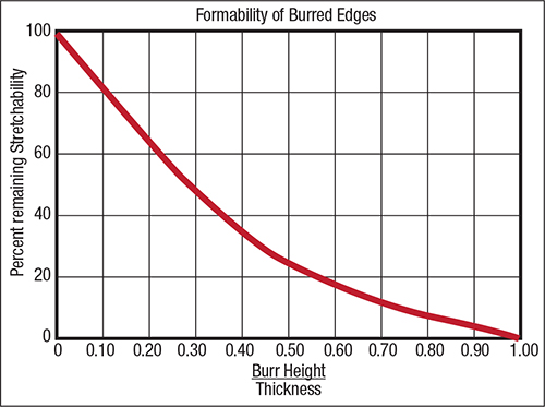
Fig. 2—Residual stretchability relates to burr height. Source: Dinda, James, Keeler, and Stine, “How to Use Circle Grid Analysis for Die Tryout,” ASM, Metals Park, OH, 1981.
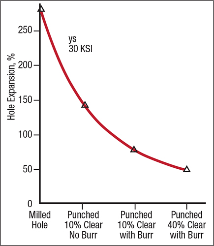
Fig. 3—Curve shows how edge damage can dramatically reduce hole expansion. Source: R.R. Hilsen, “Proceedings of Microalloying 75,” New York, NY, 1977.

Fig. 4—Milling one-half tensile samples with a sheared edge and a milled edge can provide quantitative data on edge damage.
View Glossary of Metalforming Terms
Comments
Must be logged in to post a comment. Sign in or Create an Account
There are no comments posted. Quality Control
Ascential Technologies Appoints Divisional CEO to Specialty ...
Wednesday, April 24, 2024
Brinell, Rockwell and Vickers Hardness Testing: Use and Misu...
Daniel Schaeffler Friday, April 1, 2022
 Quality Control
Troubleshooting Sheet Metal Forming Problems, Part 2: The St...
Daniel Schaeffler Friday, February 26, 2021
 Quality Control
Cobot Setup Offers Pick-and-Place for Material and Product S...
Wednesday, April 29, 2020
 Video
Video