 Stephen Andrassy
The Secrets to Successful Resistance Fastener Welding
May 1, 2014Comments
For the most part, the resistance-projection-welding (RPW) process is very similar to the spot-welding process. During spot welding, the size of the contact surface of the electrode cap determines current flow, while during RPW current flow is directed by the projections of the fastener. While AC and DC power sources suit RPW of fasteners, the choice of AC or DC depends on workpiece-material composition along with projection size and torque requirements.
Common Projection-Welding Challenges
While the basic process for the projection welding of nuts and studs may be simple, when fabricators fail to follow a few standard guidelines, several problems may occur. For instance, you might develop weld spatter in the threads, or experience hole misalignment. Cold welds and thread distortion also may occur. Undetected, these problems can easily result in lost production time and scrapped parts, which will end up costing manufacturers money that cannot be recouped until the issues are corrected. The good news: By following just a few simple recommendations, fabricators can avoid these problems and successfully—and profitably—projection-weld nuts and studs. Simple Setup Guidelines RPW of a nut or stud occurs in three distinct phases. First, the upper electrode of the welding machine holds the fastener projections in place to the stamped metal part. The machine then applies current and begins to heat the projections to the prescribed welding temperature. Finally, force applied to the electrode causes the heated projections to rapidly collapse, and fusion of the two takes place. To achieve a successfully projection-welded part, adhere to the following guidelines. First, ensure that the welding machine is correctly sized for the particular fastener being welded, and that the required welding conditions fall within the normal operating range of the machine. The frame of the welding machine and the electrode assembly must be rigid to avoid flexure and misalignment under load. The electrode force must be able to hold each projection firmly against the stamping during the initial period of the weld time, and must have good follow-up characteristics when the projections collapse during the welding process. Slow follow-up will result in metal expulsion before the parts come together. Also ensure that the surfaces of the electrodes are flat and well-aligned. They must have clean contact points and be free from oil, dirt or film. The upper electrodes also must be on the same centerline. While most RPW setups employ Class 2 copper-alloy electrodes, harder tungsten-copper inserts can be used to minimize electrode wear. The weld pin of the lower electrode should be of a properly insulated material, either ceramic or a material with a nonconductive coating. Finally, the weld pin should be spring- or air-loaded. Incorporating an air-supported pin not only will help cool the weld, it also will expel any weld spatter that might occur. Follow the Prescribed Welding Procedure To determine the optimum weld schedule—electrode force, weld time in cycles and welding current—first consider the type of nut or stud to be welded, along with the size and location of the projections. Then consider the thickness and material grade of the stamped part. This information also allows a fabricator to establish a typical minimum torque-to-failure test for the settings selected.
To verify that a minimum specified torque is achieved with the parameters selected, destructive testing most likely is required. Fabricators typically use either a push-off or peel test to check that a piece of the material can be pulled from the sheet at each projection point. If this cannot be accomplished, the welding parameters (electrode force, weld cycle time and current) can be adjusted to reach the desired torque requirements. Typically, a short weld time (in cycles) requires more current, and a longer weld time requires less current. For most applications, the current required for RPW is less than what is required for corresponding spot welding. RPW current must be sufficient to create fusion before the projections completely collapse. While shorter welding time is desirable from a production standpoint, higher current is necessary to create quality welds. To prevent overheating and metal expulsion, take care to optimize the weld schedule. To weld fasteners to high-strength steels, consider using impulse welding to better control heating rate. Ensure that electrode force is sufficient to flatten the projections completely when they reach welding temperature, and that the fasteners are brought into contact with the metal stamping. Conversely, excessive force will prematurely collapse the projections and lead to incomplete fusion.
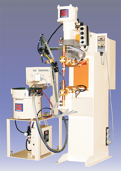
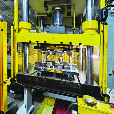
To achieve a successfully projection-welded part, the welding machine must be correctly sized for the particular fastener being welded. The frame of the machine and the electrode assembly must be rigid to avoid flexure and misalignment under load. Shown: a single-point projection-welding system combining a pedestal welder and nut/bolt feeder.
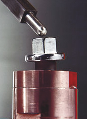
The dolphin-nose shape of this nut guide pin keeps the weld nut centrally located on the guide pin. Air pressure holds the guide pin in the up position. When the upper electrode pushes the weld nut and guide pin down, air passes around the guide pin to blow a any weld spatter, help prevent the guide pin from sticking, cool the tooling and minimize electrode-cap wear.