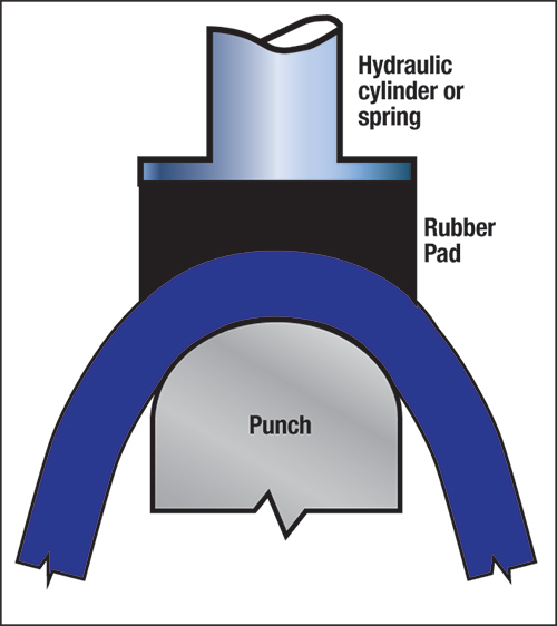
For the bending problem in Fig. 1, metalformers typically apply a high-durometer rubber pad to the flat blank and force the pad to maintain blank-to-punch contact with a hydraulic cylinder or stiff spring (Fig. 2). The cylinder or spring contributes additional energy to the forming process, as required by Mother Nature.
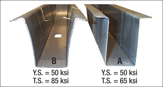 |
Fig. 3—The die was adjusted to provide nearly zero springback for material A. When material B was placed in the same die without any process changes, severe sidewall curl resulted. Material B had a higher n-value and more workhardening. Courtesy of WorldAutoSteel—AHSS Application Guidelines ver. 4.0.
|
Rule 3: When the forming forces release, the stamping will take whatever shape it can to minimize residual stresses.
This shape change, called springback, can occur in several forms including angular change, sidewall curl, twist, global shape change and surface disturbances. Formed channels or beams are highly susceptible to sidewall curl (Fig. 3). Channel A was formed by a specific process designed for steel with 50-ksi yield strength and 65-ksi tensile strength. These numbers provide a rough estimate of the workhardening exponent (n-value).
Now observe the major sidewall curl in channel B. Yield strength equals that of channel A, but its tensile strength is higher. The TS/YS ratio for channel B is higher than channel A, indicating a different forming process, a higher n-value, and a stronger material exiting the forming process. The residual stress balance of channel A is lost as channel B seeks its own minimized residual stress forming mode.
Rule 4: Within the stamping, positive residual stresses must be balanced by negative residual stresses. 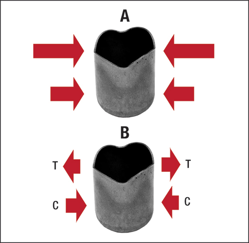 |
| Fig. 4—While still in the die (A), the cup has complete circumferential compressive stresses. When released from the die (B), the upper portion of the cup expands to release the compressive stresses. The upper part then goes into tension to balance the residual compressive stresses still trapped in the cup. |
Schematic A of Fig. 4 shows the elastic stresses in a deep-drawn cup while still in the forming die. The wall is created from sheetmetal originally in the blank. This material must compress as the circumference of the blank becomes smaller in its journey to the die radius. The material at the top of the cup must travel the furthest, and so must compress the most to create the largest compressive elastic stresses.
When we remove the cup from the die, these elastic stresses attempt to reach zero. However, the geometry of the cup only allows the cup circumference to increase (springback). The upper sections of the cup height are less constrained, allowing the elastic stresses to reach zero at the upper rim first. However, while the lower sections of the cup still have compressive stresses attempting to reach zero, they are more geometrically constrained. These lower zones force the upper zones to continue expanding, generating tensile elastic stresses (Fig. 4 schematic B). When the tensile elastic stresses balance the compressive elastic stresses, the cup stops changing shape.
Rule 5: Any subsequent modifications to the stamping will change the residual elastic stress state and therefore the shape of the stamping.
Redraw the cup, trim the top of the cup, punch a hole, weld on a bracket, heat the cup or any other modification and the cup will change the shape and residual-stress pattern. That is why stampings matching part print after the first form operation usually do not end up with the specified dimensions in the final product. Some post-forming operations can even create new elastic stresses that interact with the previous stresses for an unpredictable shape change. To compound the problem, we cannot see or measure these stresses—especially in the press shop. MF Technologies: Quality Control


 Stuart Keeler
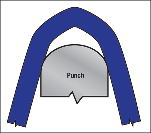

 Video
Video