


 Peter Ulintz
Managing Press Loads
January 1, 2011Comments
Limiting the working loads of your presses to 80-percent of the maximum rated capacity is a common practice with many companies to ensure long machine life. But press selection often is determined by process engineering or tool engineering prior to tool construction. At this early
phase of die development actual pressing forces only can be estimated. Only after the die is built and set in the press for the first time can the actual stamping loads be determined using press tonnage monitors. If actual tonnage exceeds the planned loading (tonnage), the die setter and engineer should consult to determine if the loading conditions are acceptable for the assigned machine. 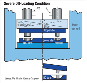
Often overlooked is the fact that an even distribution of the work load across the slide face (ram) is equally important. Ignoring load distribution can lead to die damage and eventually press damage, even when stamping loads remain well below the maximum rating of the press.
Maintaining the correct punch-to-die clearance is a primary concern for producing high-quality stampings. When the working forces in a stampings die are not distributed evenly across the press slide, the slide will tip and move laterally in the direction of the greatest force. When the load is not centered under the press ram, critical die clearances may be altered. If this movement occurs while punches are engaged with other die components, excessive wear or damage can occur. Rapid die wear increases die maintenance costs and compromises the dimensional consistency of the stampings being produced. Unfortunately, some tooling engineers, process engineers, and setup personnel may not be aware of the negative effects of off-center loading on part quality and die life. As a result, dies will be designed, manufactured and installed in presses without consideration to centering the load.
It is important to understand that a centered load and a centered die are not the same thing. The figure depicts a simple die that is centered in a press. The punching action generates a 100-ton load on the left side of the die and a 50-ton load on the right side, even though both punches are equally spaced from the press centerline. This situation generates a very large left-to-right tipping moment because the load on the left side of the press is twice as large as the load on the right.
When the right punch fractures the material, energy is released and this creates a reverse-loading condition. The downward force on the right adds to the clockwise tipping moment, further increasing non-parallelism of the slide. As a result, the right punch enters the lower die at an angle, creating excess punch wear and possible punch chipping.
As the press continues to develop the 100 tons of force necessary to punch the remaining hole, the left punch begins shearing the material at an angle and the clockwise tipping moment continues to act on the slide. The snap-through load on the left side of the die now creates a downward force twice that of the right side. The end result is that the punches will enter the lower die at an angle and then willtip in the opposite direction while they still reside in the lower die. This leads to excessive die wear, damaged punches and poor part quality.
The real problem occurs when attempts are made to improve die wear, reduce punch damage and improve part quality. Without an understanding of the actual load distribution across the press slide, these problems cannot be solved properly. New tool steels may be tried, different punches may be purchased or, worse yet, additional clearance may be added to the side of the die opening that keeps shearing. Eventually, a burr problem develops on the other side of the die opening because the clearance is too great due to the punch tilting when it cuts. As punch wear continues to be a problem, specialized surface coatings may be applied to the punches.
After a lot of work, effort and frustration, some improvements might be realized. But if a little effort were spent upfront to correct the off-centered loading conditions, all of this other work would be unnecessary. MF
Technologies: Tooling
Comments
Must be logged in to post a comment. Sign in or Create an Account
There are no comments posted.
 Stamping Presses
Increasing Press Speed and (In)Efficiency
Peter Ulintz Thursday, March 30, 2023