
Bendability and total elongation show a correlation. Imagine a tensile-test sample just under the outer surface of a bend sample. Since the higher-strength steel has a lower total elongation in tension, it has reduced bendability (outer-fiber stretch) as reflected in the bend radius/sheet thickness ratio, R/t. Therefore, higher-strength steels require a larger bend radius to avoid cracking and tearing at the outer surface of the bend.
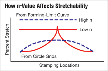 |
| Fig. 2—Schematic shows reduced stretchability and increased strain-gradient severity as the n-value decreases with increased steel strength. |
Cup-drawing severity usually is measured by the limiting draw ratio (LDR) that determines the maximum blank diameter that can be successfully drawn into a cup with a given punch diameter. The LDR tends to be independent of steel strength for all hot-rolled and higher-strength-steel products. A simple analysis shows that the stronger steel moving in from the binder balances with the same stronger steel near the punch radius where failures usually occur.
Deep drawing generally refers to a square or roughly rectangular box. The corners, or the box, comprise one-quarter of the cup-drawing operation. However, most punch radii, embossments and other geometrical features combine bending and stretching, and become more likely to fail with increases in steel strength.
Summarizing formability of higher-strength steel, any area of the stamping subjected to a tensile stress and the resulting sheetmetal thinning becomes more critical as steel strength increases.
Springback
The atoms in steel bind via extremely strong elastic stresses. Applying a force to the steel generates a stress on the atomic structure. Tensile stress causes an increase in atomic spacing, while compressive stress causes a decrease. Remove the stress and the atoms return to their normal spacing, achieving a neutral stress state. This return to normal atomic spacing causes springback, the amount proportional to the yield stress of the material. Doubling the yield strength of steel doubles springback (Fig. 3).
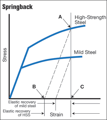 |
| Fig. 3—Springback is proportional to yield strength and increased flow stress (A). |
As flow stress increases, resulting from cold working the material, elastic stress continues to increase proportionally with the flow stress. Therefore, the potential amount of springback in a stamping varies with location within the stamping. However, if the shape of the stamping now creates a geometrical restraint that does not allow all of the elastic stresses to return to their neutral stress state, those remaining elastic stresses remaining in the stamping become residual or trapped stresses. These trapped stresses cause additional springback during subsequent stamping operations.
Most experience with springback and springback compensation arises from work on mild steel with yield strengths in the range of 25 to 35 ksi. Different grades of high-strength low-alloy (HSLA) steels have yield strengths from 35 to 100 ksi. Some of the newer advanced high-strength steels (AHSS) have minimum yield strength of 200 ksi. (These AHSS are discussed further in the Science of Forming column on page 32 in this issue.)
Thermal Effects
Materials with higher yield strength obviously requires a greater force to create the same amount of strain. Less obvious: the increased energy required to deform each stamping. The energy required is proportional to the area under the true stress-strain curve, similar to that shown in Fig. 3. Both the greater force and energy required to form higher-strength steels have a major impact on die design and press selection. The increased energy imparted during forming creates internal heat that causes a temperature increase in the stamping. This temperature increase decreases steel strength. If the temperature of the whole sheet increases, the problem generally is limited to degradation of the lubricant or a change in die dimensions.
However, if a sharp gradient develops at some location in the stamping, a more serious problem presents itself. For example, observe the solid line in Fig. 2 that represents strain values measured from circle grids imprinted into the blank. When the gradient first develops, more strain occurs in the gradient than in the rest of the stamping. More strain means more local concentration of energy and creation of localized heat. Heat reduces the strength of the steel in the developing gradient, causing more strain to localize in the gradient. The cycle constantly repeats until a severe gradient of surface strain and accompanying thickness reduction too often leads to a local failure site (Fig. 2). Once a severe gradient develops, the severity of the gradient (height) can change drastically during production runs, causing dramatic shifts in stamping dimensions and process control.
Lubrication
Forming higher-strength steels requires better lubricants. The thermal effects described above can cause major reductions in lubricant viscosity, or even lubricant breakdown. Given the reduced stretchability of higher-strength steels, one function of the dies is to allow more sheetmetal to flow into the die from the binder area to help create the required lengths-of-line. As the higher-strength steels become hotter, many lubricants tend to increase their friction characteristics and retard material flow.
When higher-strength steels are pulled over die and punch radii, the increased interface force multiplied by a constant coefficient of friction creates a higher frictional restraining force—the opposite of the desired goal. When steel temperature increases, the coefficient of friction increases or breaks down. First comes burnishing of the sheet surface, then galling, followed by scoring, and finally seizing.
Corrective action includes use of dry-barrier lubricants that completely separate the die surface from the sheetmetal surface. A very low coefficient of friction plus insensitivity to temperature changes makes these lubricants ideal for worst-case scenarios.
Hardness
We place too much emphasis on the hardness of higher-strength steels rather than their strength. Sheetmetal fails due to tensile stresses elongating the length-of-line accompanied by sheet thinning. These tensile stresses measure the strength of the steels. In contrast, different hardness tests force different sizes and shapes of indenters into the material surface under specified load sequences. Compression pushes aside the material under the indenter. Finally, the size of the crater is measured and used to specify the material hardness. Failure occurs via tension and thinning and must be measured by the same mode of deformation. The hardness test, a compressive mode, mimics the reaction of the surface to damage by the typography (peaks and valleys) of the die surface. Therefore, hardness tests provide an excellent means to determine resistance of a surface to wear. The correlation between material hardness and formability is extremely poor.
Virtual Metalforming
Evaluation of different types of steel alloys is extremely difficult in physical press shops. Obtaining trial-sized coils or blanks can be expensive and time consuming—sometimes taking months. Then, upon receipt of the trial steel, the actual coil properties may differ significantly from the ordered properties. Dies may require grinding, welding or even complete rebuilding.
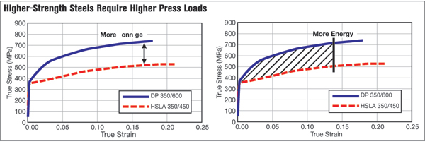 |
| Fig. 4—Tonnage is a function of peak stress (load) but energy is a function of the entire area under the true-stress true-strain curve. |
In the virtual world, however, we change the strength or other properties of the steel by simply retyping new properties into the program and clicking Run. The major benefit: evaluating the effect of the steel properties and lubrication before even starting to build the physical die. A series of entries on the keyboard cue the performance of what-if scenarios. However, even forming in the virtual world requires accurate properties of the production steel for accurate computation. Without the steel properties, every trial is simply a guess—in the virtual and in the physical worlds.
Press-Line Considerations
The increased forces needed to form, pierce and trim higher-strength steels creates significant problems for pressroom equipment and tooling, including excessive tooling defections, damaging tipping moments, and amplified vibrations and snapthrough forces that can shock and break dies—and sometimes presses. Stamping higher-strength steels can affect the size, strength, power and overall configuration of every major piece of the press line, including coil-handling equipment, coil-feed systems, straightening machines and presses.
Because higher-strength materials require more stress to deform, additional servo-motor power and torque capability may be needed to pull the coil material through the straightener. Increasing the back tension between the coil-feed and straightening equipment also may be required due to the higher yield strength of the material in the loop—the loop material may try to push back against the straightener or the feed system. Insufficient back-tension could cause material slippage through the straightener. As coil diameter decreases, the straightener loses the mechanical advantage it had at a larger coil OD; thus, back-tension force must decrease. Fortunately, modern technology provides electronic coil-handling control options that automatically provide such compensations.
Nowhere in the coil-feeding system will higher-strength materials require more attention than in the coil straightener. Straighteners are recognizable by their large roll diameters and relatively wide spacing. The roll diameters and center distances vary depending on material thickness and coil width. The rated capacity of most pressroom straighteners is based on processing mild steel with yield strengths below 340 MPa. Higher-strength steels, due to their higher yield strengths, have a greater tendency to retain their coil set. This requires greater horsepower to straighten the material within an acceptable level of flatness. Larger-diameter rolls and wider roll spacing also are required to work the material effectively. Increasing roll diameter and center distances on straighteners to accommodate higher-strength steels will limit the range (thickness and width) of materials that can be straightened effectively.
As a general rule, higher-strength materials require straightening equipment that can process an equal width of mild steel at least 50 percent thicker. This allowance ensures proportionally larger journals and straightener rolls, preventing the journals from being overly worked by the stronger higher-strength materials. Larger rolls and journals and broader center distances safeguard the straightener from potential damage caused by these additional stresses.
Cutting, blanking and piercing stresses produce unloading forces, known as snapthrough or reverse-tonnage forces, in stamping presses. Because higher-strength materials require greater stress to blank and pierce as compared to mild steel, they generate proportionally increased snapthrough forces.
High-tensile snapthrough forces can introduce large downward accelerations to the upper die half. These forces work to essentially separate the upper die from the bottom of the ram on every stroke. If using a hydraulic or screw die-clamping system without sufficient clamping force, the upper die half could separate from the bottom of the ram on each stroke, causing additional punch penetration and fatigue to the upper-die-mounting fasteners.
Stamping higher-strength steels brings obvious concerns with press capacity, or tonnage. Less obvious, but of primary concern: the available press energy to carry out the stamping process. Understand this: Press tonnage and press energy are not one in the same.
The greater ultimate strength of higher-strength steels require greater press loads as well as greater deformation energy, proportional to the area underthe true-stress true-strain curve (Fig. 4).
Die-Design Considerations
In general, the beneficial properties of higher-strength materials—high yield strength, high tensile strength and high hardness—also contribute to degraded tool life and premature failures. Tool-failure mechanisms common to higher-strength materials include chipping, cracking and wear in piercing, shearing and trimming operations. Predominant mechanisms during forming operations include galling and wear.
Cutting, Punching and Trimming
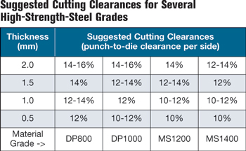 |
The higher stresses needed to penetrate stronger materials require additional cutting clearances between the punch and die as compared to those required for mild steel. The table, Suggested Cutting Clearances for Several High-Strength-Steel Grades, provides some recommended cutting clearances for several high-strength grades. Excessively tight cutting clearances often lead to increased galling and chipping. But when cutting clearances are too large, cracking may result. Plastic deformation of the tools also can occur if process stresses exceed the compressive strength of the tool steel.
Tool wear becomes a major issue when stamping higher-strength steels, and this wear is characterized as either abrasive or adhesive. Abrasive wear occurs when the tool material wears a, typically by friction. Reduce abrasive wear by increasing the tooling material’s hardness or carbide volume, although that will reduce its toughness and resistance to adhesive wear. Adhesive wear results from microscopic welding at localized contact points between the tool and work-material surfaces. Reduce adhesive wear by increasing the toughness of the tooling material and by reducing the friction between the tooling material and workpiece. This usually requires the proper selection and use of lubricants, tool steel and tooling-surface treatments.
In general, the best overall punch performance for blanking, piercing and trimming is achieved through a combined balance of tool-steel toughness and wear resistance.
General guidelines for cutting, punching and trimming:
- Trimming steels should be adequately supported and keyed, pocketed or heeled whenever possible to avoid flexing and tipping due to side thrust.
- Consider upgrading tool steels to at least one grade level higher as compared to mild steel.
- Consider powder-metallurgy tool steels, as they often are more economical in the long run due to their low wear rate, and consider tool-surface coatings to maximize tool life.
- Avoid tight corner clearances that can eventually lead to excessive burring.
- Provide a shear angle of two to four times material thickness over 12 in. of trim length to reduce press tonnage and extend die life.
- Balance shear angles over the length of the cut to prevent sides movement of material by a single-angle shear.
- Reduce die maintenance by avoiding knife-edge conditions in trim steels —perform all trimming at 90-deg. angles to the trim surface.
- Design unusual shapes or notch conditions with inserts, and consider those inserts perishable.
- Pierce holes that are equal to or less than material thickness should be pierced at 90-deg. angles to the surface; holes greater than material thickness should be pierced no more than 10 deg. off-angle.
- Keep punch-head pressures below 40,000 psi to minimize head breakage, and use hardened backing plates when punch-head pressures exceed 20,000 psi.
- Keep punch-point pressures below 60 percent of the compressive strength of the punch body to minimize punch-point breakage and deformation (consult your punch manufacturer for details).
- Avoid use of urethane strippers with higher-strength materials; these materials require hardened strippers with mechanical or nitrogen-gas springs due to the higher stripping and holding forces.
- Develop trim edges whenever possible, as trimming after forming greatly increases tool wear due to high workhardening.
Bending, Flanging and Forming
All metalforming includes some form of bending—often the predominant feature in a stamping. Elastic springback als occurs after bending and forming at room temperature, and can be considerable with higher-strength steels. Small bend radii reduce the ratio of elastic to plastic strains within the bend, thereby reducing the magnitude of springback. But exercise caution, as a smaller radius also increases the amount of force required to deform the material and also increases forming severity throughout the thickness of the material.
Wiping dies require the use of pressure pads to keep part material from slipping when formed. Pad pressures for wiping dies generally equal the punch force required to form the part. Because higher-strength steels can have two to three times the initial strength of mild steels, the required pressure-pad force could be as much as 300 percent greater. This level of holding force may be difficult to achieve in small wiping dies or in a small die area.
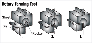 |
| Fig. 5—Consider rotary forming tools in place of wiping dies. |
Incorporate over-bending into wiping dies to compensate for springback. Expect as much as 10 deg. of springback depending on the steel grade. Higher forming stresses on die materials can create potentially large tool deflections. Key and properly heel forming steels to control tooling deflections and maintain part quality.
Where practical, consider rotary forming tools (Fig. 5) in place of flange-wipe dies. Rotary bending enables easier adjustment of springback compensation while tensile loading, generated by the wiping tool, is absent.
General die design considerations for bending and forming:
- Minimize punch radii, as they affect springback.
- Design small replaceable sections in high wear areas—use inserts for radii and flange adjustments.
- Ensure that die sections have adequate aspect ratios (width to height) with heels and keys to resist thrust forces during forming.
- Consider higher grades of die material, at least one tool-steel-grade higher, and coat flange steels, preferably via a vanadium-carbide process.
- Use material gainers to increase length of line in low-strain areas to feed high-strain areas in flanges.
- Avoid placing trim bypass (mismatch) in stretch or compression areas of the flange to help avoid splitting.
- Try to ‘fold’ the material around a radius, instead of drawing or stretching, to reduce sidewall curl.
- Flatten the flange radius at the bottom of the press stroke.
- Bottom the pad and all forming steels at the bottom of the press stroke.
Draw Forming
Higher-strength steels require careful planning and consideration before choosing draw forming as a method of manufacture. Metalforming simulations allow exploration of different forming processes by predicting strains and residual stresses for different deformation modes. Deep drawing over a binder and through draw beads may not be the best choice and simple die forming or rollforming may offer better options for some very-high-strength steels.
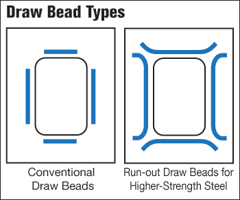 |
| Fig. 6—Traditional draw-bead layout and special run-out draw beads for higher-strength steels. Auto-Steel Partnership Design Guidelines. |
In draw development, maintain even draw depths and constant length-of-line to the greatest extent possible, and form as much of the part as possible to the full depth in the first forming operation. Controlling material flow may require an increase in binder tonnage by as much as 20 percent when compared to working with conventional HSLA steel grades, and double that needed for mild steels. In the right press, these are not overwhelming issues. However, a single-acting press with a nitrogen cushion may be insufficient for draw forming some higher-strength grades.
In single-acting presses, high impact loads on the die and press occur high up from bottom dead center where drawing typically begins. The impact occurs at a point in the press stroke where slide velocities are higher and available tonnage is de-rated. Under these conditions, mechanical presses invite damage due to large shock loads. Double-action presses employ an outer slide capable of generating the forces needed to set draw beads near bottom dead center, taking advantage of full-tonnage availability and low slide velocity. This minimizes shock loads to the die and press, and shock loads here will less likely exceed the rated capacity of the press.
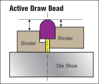 |
| Fig. 7—Use active draw beads to achieve adequate strain levels to reduce sidewall curl and possibly eliminate the need for a second post-stretching operation. |
General die design considerations for draw forming:
- Design small replaceable sections in high wear areas.
- Consider die coatings for high wear areas.
- Correct high strain and thickening in the product design by increasing radii and softening geometry features.
- Add take-up beads in high-compression areas to avoid wrinkles and buckles.
- Draw as much of the part as possible in the first forming tool.
- Equalize depth of draw as much as possible using a curved binder, addendum and/or gainers.
- Design addendum to provide nearly constant lengths-of-line to help minimize springback—open-ended draws often help minimize forming problems.
- Do not rely on a restrike operation to move previously workhardened materials after initial draw—use restrike dies only to coin radii, adjust angles, or add darts and embossments.
- Higher binder pressures required to suppress wrinkles increase die wear, so consider higher grades of die materials, at least one tool-steel-grade higher.
- Plan for several recuts when designing draw-form stations by increasing pad thickness, post thickness, insert thickness, etc.
- Draw beads should ‘run out’ at the tangent of the corner radius to minimize compression in the corners (Fig. 6).
- Optimizing the shape and size of blanks can reduce reliance on draw beads that can substantially workharden the material.
- Consider hydraulic or double-acting mechanical presses for deep draws.
- Consider using active draw beads (Fig. 7) to achieve adequate strain levels to reduce sidewall curl and possibly eliminate the need for a second post-stretching operation. Active draw beads increase penetration into the flange material near the bottom of the stroke to restrict material flow into the die cavity. This restriction causes the material in the sidewall to stretch, which works to balance the stresses in the wall.
Work Together
Working with higher-strength materials will require stamping companies and tool and die shops to work closely with higher-strength-material producers and tool-steel suppliers in order to select the proper tool steel, heattreatment and surface-coating application appropriate for the sheet-material type and strength levels being processed. MF
View Glossary of Metalforming Terms
Technologies: Materials, Quality Control, Tooling