Maintaining Servo-Driven Presses
May 22, 2019Comments
Servo-driven presses offer improved control during the feed cycle while allowing for the stroke to be adjusted to allow for long feed lengths and the manufacture of complex stampings. While the investment on the front end runs higher than with standard mechanical presses, the rewards are worth it—so long as you understand the technology, operation and maintenance requirements. Armed with this knowledge, metal formers know what to look for and what to ask as part of an ongoing maintenance program.
Let’s learn.
Structural Features and Frame Design
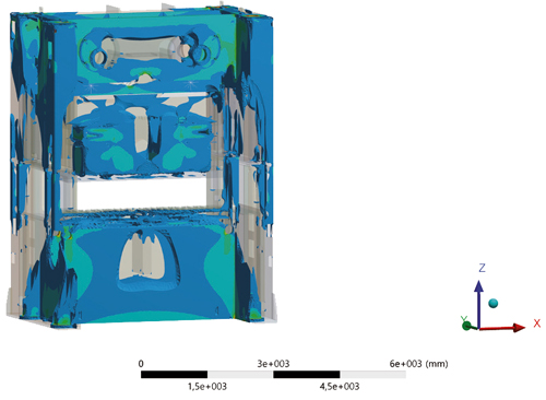 |
| Some manufacturers ensure press longevity by performing finite-element analysis (FEA) on the press frame, drive components and slide assemblies to optimize construction and prepare the frame for dynamic forming processes. |
Drivetrain Deciphered
The use of dynamic torque motors in servo presses delivers several advantages:
- High torque available at low speeds;
- Low moment of inertia, very dynamic;
- Extremely quiet as compared with standard mechanical presses;
- Temperature-controlled, water-cooled;
- Shorter brake angle;
- No backlash or rotor losses;
- Nearly maintenance-free operation; and
- Long production lifetime.
Most servo-driven presses still use a gear reduction, particularly on larger two- and four-point presses. The drivetrain, characterized by one or more torque motors attached to the drive shaft and the absence of a traditional flywheel assembly clutch/brake combination, ensures high dynamics, efficient processes and reduced maintenance due to the absence of these mechanical-press features.
As for the braking action, that’s performed by the motor itself. Presses with higher tonnages and correspondingly heavier slides have an additional hydraulically released and spring-loaded holding brake specially developed for servo presses. This prevents slide movement during drive inactivity or a press-system failure.
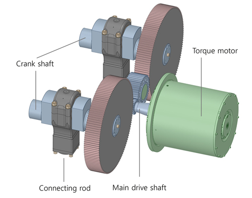
The servo drive, which controls press movement, allows the press drivetrain to move in either direction during the stroke. Photo courtesy of Simpac.
While drivetrain designs from different manufacturers vary slightly, all share these attributes:
- Programmable stroke and speed;
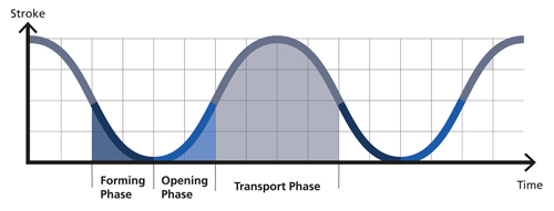
- Pendulum motion;
- Dwell or holding function with full press force at bottom dead center, which enables reliable integration of other processes such as nut and stud feeding, in-die welding or in-die tapping; and
- Time-saving setup features and tryout processes for improved safety due to the availability of full-press force at low speeds.
These attributes enable greater precision of produced parts and increased output rates. Slide motion control results in less die wear and maintenance.
The drive capabilities described above enable the following to be performed with a servo press:
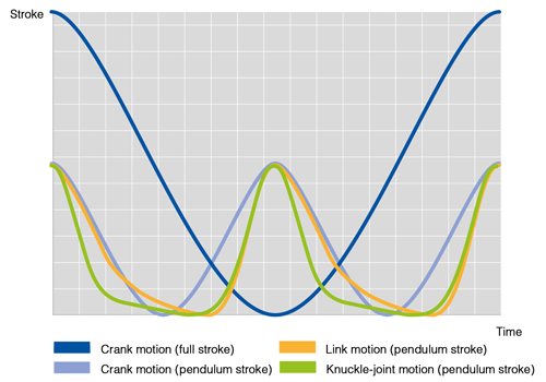
- Crank motion (sinusodial curve shape);
- Transfer mode (allows for the adaption of the slide motion to the required feed length);
- Drawing and fine blanking;
- Cutting and coining; and
- Pulse-mode-vibration forming.