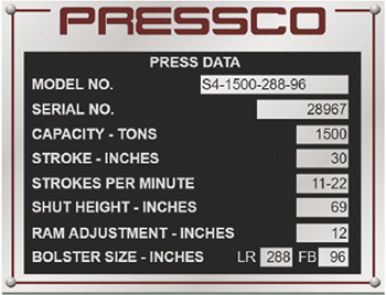
The press shut height listed on the specification plate is its maximum height. The ram has an adjustment screw that can be turned manually or by an electric motor to adjust the ram position downward to reduce the press shut height. The maximum amount of adjustment is determined by the adjustment-screw length. The maximum adjustment also is listed on the press-specification plate.
Die Height vs. Die Shut Height
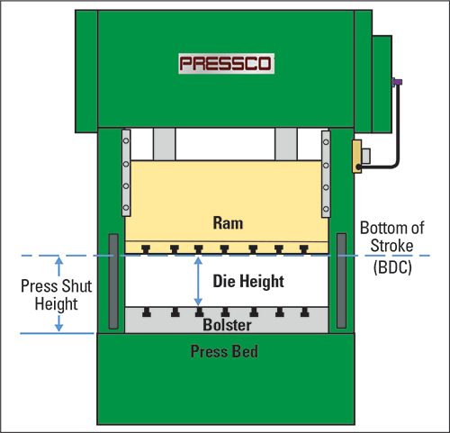
A bolster plate attaches to the press bed in a manner that allows it to be removed, replaced or exchanged. Some presses have rolling bolsters that move in and out from under the ram to facilitate quick die change. Because bolsters are removable and exchangeable and also can vary in thickness, they directly affect the available die-height space under the ram.
|
| Fig. 2—Press data specification plate |
Die height is defined as the distance from the bottom face of the ram to the top of the bolster, with the ram positioned at the very bottom of its stroke. Calculate maximum die height by subtracting the bolster thickness from the press shut height. To obtain minimum die height, subtract the ram-adjustment length from the maximum die-height distance.
Die shut height refers to the overall height of a die assembly in its fully closed (home) position. This includes any unsecured parallels or risers added above or below the die.
The die-shut-height dimension must fall within the minimum and maximum die-height space in the press. If the die-shut height is greater than the die-height space in the press, the die will close fully before the ram reaches the bottom of its stroke. This causes the press frame to stretch and the connections (pitman) and die assembly to compress, generating excessively high tonnage forces and potentially causing damage to the die and press.
If the die-shut height is less than the minimum die-height space in the press, additional parallels or risers must be added until the overall shut height exceeds the minimum die-height distance.
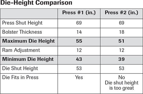 The Die-Height Comparison table illustrates a problem that can arise during die change when two presses, both with the same shut-height and ram-adjustment specifications, are assumed to be capable of running a common die assembly without calculating the die-height space for each press.
Shut-Height Calibration
With die setup complete and the press fully loaded, a final calibration of the press shut height may be required. Why? As the press cycles, force applied to the ram and the bolster plate cause both to deflect slightly. This deflection prevents the die from closing fully. Lowering the ram slightly to calibrate the shut height ensures fully closed dies.
To measure the die-shut height and to make final ram adjustments, use solder strips and set blocks (stop blocks) with grooves ground into the top surface. No industry standards exist for the depth of the set-block groove, but the objective is the same for any groove depth.
For example, consider a progressive die with four set blocks precision ground to an overall height 0.005 in. less than the inside shut height would be for the coil thickness at the low limit. This height assures that the set blocks never hit home, even with minimum material thickness.
Grinding a 0.045-in.-deep groove into the top of each set block results in a groove bottom that rests 0.050 in. from the upper die surface (0.045-in. groove + 0.005-in. clearance). When the die-shut height is correct for low-limit material thickness, the thickness of the solder strip will measure 0.050 in. after the press cycles. If the next coil of material checks 0.003 in. above the low limit, the shut height will be adjusted until the solder thickness measures 0.053 in. after the press cycles.
If bend angles on the production piece part are not proper, do not attempt to correct them by raising and lowering the ram. Instead, since you have verified that the shut height is correct for the material thickness in the die, add or remove shims from under the forming punches to correct the bend angles.
For dies not designed and built for easy in-press adjustments, metalformers often take shortcuts such as moving ram—the first steps toward compromising die timing. This ultimately results in excessive tonnage, inconsistent part quality, poorly performing dies and reduced die life. MF
Industry-Related Terms: Bed,
Checks,
Compress,
Die,
Dimension,
Forming,
Plate,
Ram,
Shut Height,
Strips,
Stroke,
Surface,
ThicknessView Glossary of Metalforming Terms Technologies: Tooling


 Peter Ulintz