Lou Kren Lou Kren
Senior Editor

The Latest in Die Design and Simulation Software

March 1, 2019
0
Comments


New Release: Integration from Quoting to Design to Manufacturing

Cimatron 14


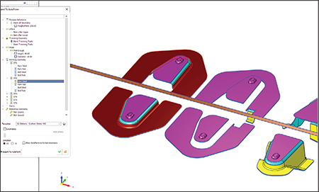
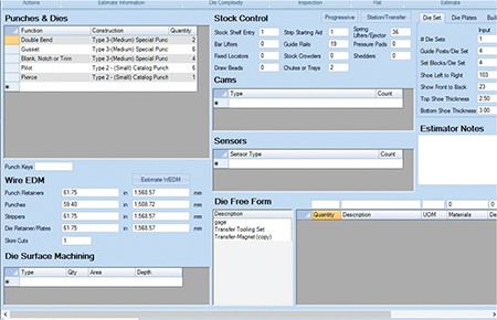
Cimatron strip design with the new Export to ProgSim dialog allows designers to validate a design before manufacturing, thus reducing iterations.
3D Systems’ Cimatron provides integration of the tool and die making process, from quoting to design to manufacturing. The latest product release, Cimatron 14, includes new capabilities that help accelerate the design and manufacturing cycle.

For example, new integration of AutoForm Prog-Sim enables users to reduce the number of iterations. Typically, the die design process consists of several production iterations of the tool or the blank in order to analyze springback effect, trim optimization and other aspects that could impact the desired result. Cimatron 14 with AutoForm Prog-Sim reduces iterations and allows the designer to validate a design before manufacturing the die. Users now can load a complete strip-design project created in Cimatron directly into the AutoForm environment, run the simulation in one continuous process, and once the result is available, read, manage and display the results in Cimatron.

Also, Cimatron 14 reportedly includes a new capability to easily define and create addendum faces between the blank faces and the binder. This is especially beneficial in transfer and regular die design where large parts transfer between multiple presses to shells, tube applications, frames and structural components.

And, Fuzzy Offset, a robust surface-offset feature, enables users to easily create an approximate smooth offset surface out of a complex skin surface. The Fuzzy Offset feature also offers a powerful option for die casting and mold design, according to company officials.

Die System Simulation Software with New Interface, Set-Up-Time Reduction


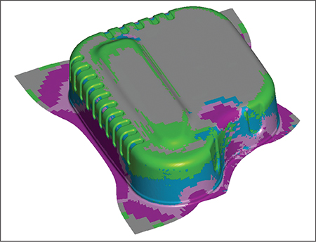
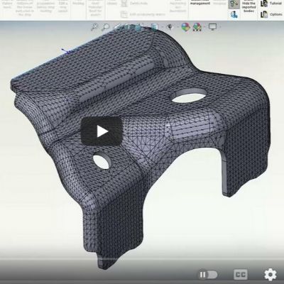
With an all-new user interface, the Dynaform 6.0 die system simulation software enables users to quickly conduct sheet metal stamping simulations to estimate the blank cost and formability of stamping parts via guided process wizards.
Dynaform Version 6.0

Engineering Technology Associates, Inc. (ETA) offers the latest release of its LS-Dyna-based, Dynaform Version 6.0 die system simulation software. Dynaform 6.0 offers an all-new graphic user interface with combined pre- and post-processing capabilities. Users quickly can conduct sheet metal stamping simulations to estimate the blank cost and formability of stamping parts using guided process wizards.

In addition, new features are included, such as a simulation data manager and Microsoft PowerPoint-based automatic report generation. The new software also consists of simplified as well as advanced customized features to reduce set-up time.

“Dynaform 6.0 will improve the efficiency and productivity of stamping engineers with no prior experience in stamping simulation,” says Dr. Akbar Farahani, CEO of ETA.

Enhanced Reverse Engineering


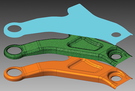
VISI now has the ability for a points cloud from a scanning or measuring machine to be loaded either directly or indirectly, and the relative mesh can be created by setting different options for refining and smoothing. This capability eases reverse-engineering tasks.
VISI 2019 R1

TST Tooling Software announces major software enhancements in the latest release of VISI software, including several for reverse engineering, along with a range of new and improved CAD/CAM functions for the progressive-die market.

As part of a larger collaboration project for reverse engineering and casting, VISI 2019 R1 introduces an extended direct interface to multiple portable measuring arms and Leica scanning devices from Hexagon. These enhancements, together with the dedicated module update, provides a reverse-engineering solution as well as the ability to generate casting and stock models from VISI’s existing modeling and machining environment.

With these updates, VISI now has the ability for a points cloud to be loaded either directly or indirectly, and the relative mesh can be created by setting different options for refining and smoothing. Surfaces can be created automatically or semi-automatically by extracting different key geometrical references from the refined mesh. Scan data, stock or reference casting mesh models easily can be aligned to the original geometrical CAD model using dedicated commands to allow comparisons, gap analysis and optimized toolpath processes, according to company officials.

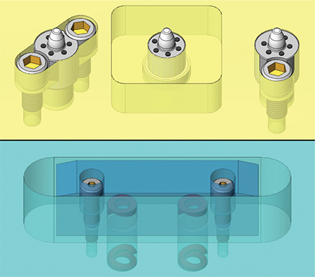
Also, the VISI blanking process has been enhanced. By simply defining the relative force to apply, faces can be set on the model affected by the pressure pad. This allows the material to flow based on the applied force on the pressure pad. And, users now can set constraints to simulate the effect of a uniformly distributed blankholder force. Now it is possible to define a friction value and the force value to be applied for the blanking phase. This leads to a more accurate blanking process, which provides additional support to the user during die design.


AutoForm R8 enables users to engineer a feasible stamping process for patchwork blanks.
Streamlined Digital Process Chain

AutoForm R8

AutoForm Engineering has unveiled AutoForm R8, delivering new features and enhancements to support customers in streamlining the digital process chain. The software, focusing on topics emphasized by users in a 32018 customer survey, is particularly beneficial for users working on topics related to progressive dies and springback compensation, as well as on parts produced from patchwork blanks, according to AutoForm officials.

With improved strip layout definition, users can define the layout for a single or double part, and then quickly evaluate and compare different nesting options. This software version allows for simple prediction of potential blank shape and nesting, the minimization of material usage, and the early prediction of part costs. In addition, the new feature for webs design enables users not only to use predefined shapes but also to model desired shapes with just a few commands.

AutoForm R8 also offers more options for springback compensation, allowing engineers to use real, as opposed to virtual, measurements for compensation. As compensation is based on arbitrary geometries, part simulation results are not required. As a result, tools can be compensated using external data from various sources, such as measurement, hemming simulation or assembly simulation. This flexibility in sourcing data for springback compensation allows users to increase their use case coverage.

In addition, AutoForm R8 enables users to engineer a feasible stamping process for patchwork blanks, as simulation now can be used as a reliable means to estimate part formability and to test various sizes and configurations.

Expanded Use of Parametric Component Insertion Among Other Enhancements


The Logopress3 Insert a Set of Components command can quickly insert a configurable set of components such as pilot lifter assemblies or bar lifters along with all holes and openings in all affected plates.
Logopress3 2019

Logopress AutoForm Group has implemented an often-requested enhancement to its SolidWorks-based Logopress3 die design software. Die designers now can use their Insert a Set of Components command to quickly insert a configurable set of components along with all holes and openings in all affected plates. For example, they can insert Standard Lifters Pilot Assemblies simply by selecting various options from dropdown lists and selecting the position(s) in the model where they want to insert the components. The moment the components are inserted, the program automatically populates the correct supplier name and part number into a special Bill of Materials that contains only standard catalog components.

Users also can insert a combination of custom-manufactured components along with their related standard-catalog components. A configurable bar lifter along with springs and shoulder bolts could be inserted, as could keeper blocks along with their screws and dowels. Also, users can create their own Set of Components, by following the company’s tutorial within the Logopress3 help file, and easily customize an existing Set of Components, according to company officials.

Logopress3 die design software includes a recently trademarked module, Die Debugger. This user-friendly module has been enhanced to include an S-curve variable that allows users to define an equation of motion with respect to a mathematical function. This is useful for many actions, including defining the motion simulation of a transfer arm whose motion must be independent of the press cycle. Die Debugger also has been significantly optimized from a performance standpoint, particularly the dynamic interference detection portion of the software.

User-Configurable Die-Estimating Software


The Die Estimate tab in Tool Planners’ DieMatrix software helps estimate processes, components and materials needed to create a die.
DieMatrix

The DieMatrix software application from Tool Planners Inc., used for estimating sheet metal stamping dies, can be configured easily to users’ standards and produces detailed reports for those planning, purchasing or producing dies or stampings. The software measures 2D and 3D files and features a detail reports generator and SQL database to rapidly produce consistent and accurate die estimates, according to company officials.

To save time, a built-in assistant suggests values for stations, pilots, wire path, sensors and stock control items. The software stores and applies die-construction and press-specification standards, automatically sizes dies, provides a detailed estimate sheet that breaks down die cost, and allows users to create and save special items.

Tables cover material and labor standards, press specifications, die-size standards, labor rates, production materials and more. Users can generate reports for die descriptions, die cost breakdowns and die specifications. MF

Industry-Related Terms: Insert, Blank, Blanking, CAD, Die, Webs, Mesh, Model, Nesting, Run, Surface, Transfer, Case
View Glossary of Metalforming Terms


See also: ETA (Engineering Technology Associates, Inc.), Autoform Engineering USA, Accurate Die Design Software, Inc., Tool Planners Inc., CAMBRIO/Cimatron

Technologies: Software

Comments

Must be logged in to post a comment.
There are no comments posted.

Subscribe to the Newsletter

Start receiving newsletters.