Peter Ulintz
Stamping Nonferrous Alloys
March 1, 2019Comments
Nonferrous metal alloys have been used since the beginning of civilization. The discovery of copper around 4500 BC marked the end of the Stone Age and the beginning of the Copper Age. One thousand years later, humans discovered that copper could be combined with tin through smelting, which began the Bronze Age.
Recently, much has been published about forming and stamping high-strength aluminum alloys, with research fueled by global automotive manufacturers and their desire to reduce vehicle mass and improve fuel economy by replacing steel components with aluminum.
Aluminum Challenges
Aluminum is one-third the weight of comparable steel stampings of the same thickness, making it an attractive alternative for mass-reduction efforts. Unfortunately, many automotive grades will form much like 100,000-psi yield strength steel and only have about two-thirds of the stretching ability. Due to planar anisotropy and forming limits, stamping aluminum successfully depends on part design, the shapes of the blanks, drawing depths, reduction ratios, wall angles and product-feature transitions. All interact to affect the cost and quality of an aluminum stamping.
Deep-drawing aluminum can be challenging when stampers have little experience with the various alloys. Depending on alloy and temper, some grades can have limiting draw ratios similar to that of steel, while others are substantially less. Consider keeping the limiting draw ratio (LDR) below 1.6 unless you have previous experience with the particular alloy. An LDR of 1.6 is equivalent to an approximate 38-percent reduction for the first draw. Subsequent redrawing percentages should be approximately 22, 17 and 12 percent, assuming that the ratio of material thickness to blank diameter is greater than 0.25.
Many die design handbooks contain draw-reduction tables. These reduction tables were developed decades ago primarily for low-carbon steel. Due to differences in work hardening behavior, surface topography and other factors, these tables should not be used for aluminum, copper, nickel or any other nonferrous alloy.
Copper Alloys: Process Considerations
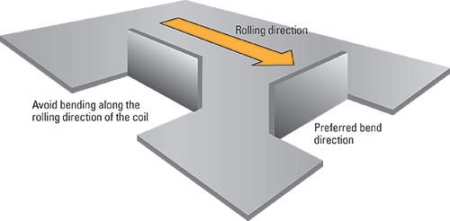
Many copper, brass, beryllium copper and nickel alloys used to produce small clips, electronic components and medical devices are produced from cold-rolled coil strip, automatically fed into progressive dies and high-speed stamping operations. The coil strip may be supplied in the annealed (dead soft) condition or a temper condition by cold working the strip prior to coiling.Cold-rolled strip typically will be more formable when bending perpendicular to the rolling direction as compared with bending along the rolling direction (see graphic). As the temper of the strip increases, so, too, does directionality. When creating a strip layout for a new part, the orientation of bending relative to the rolling direction of the coil is important because many dies are inadvertently designed with the part oriented so that bending occurs in the direction of less formability.
Coils procured in the full-annealed condition, or when the ratio of the inside bending radius to the strip thickness (R/t ratio) is relatively large, directionality may not be a problem. Conversely, when the product designer, process engineer or tooling engineer specifics a tight bending radii to control springback, the direction of bending can be critical.
The width of the strip used to make the component part also can affect formability, increasingly more important with the trend toward smaller electronic parts. Narrower strip can make sharper bends, but the effect is significant only when the strip becomes quite narrow. For example, when the width- to-thickness ratio drops below 8:1, more localized necking occurs and thus sharper bends become possible, according to the Copper Development Association Design Guide. Clean cut edges become important at this ratio with fractures likely to initiate at the edge.
The formability of copper and copper alloys (including bronzes and brass) depends on alloy and temper. Some alloys, such as C51000 (phosphor bronze 5 percent), can display very significant directionality after rolling.
For deep drawing applications, the deepest draws occur with alloys C52100 (phosphor-bronze 8 percent), followed by the brasses in order of decreasing zinc level. The LDR of cartridge brass (C26000) increases with increasing grain size.
Beryllium copper (BeCu) in the cold worked condition exhibits sharper cuts and less burrs than in the aging tempers. NGK Berlyco recommends a punch-and-die clearance of 5 to 10 percent of material thickness per side. When using dead soft (annealed) material, clearance should be reduced to 5 to 6 percent per side. Carbide tooling can be used where delicate parts with superior finish, or a high degree of dimensional precision, is required. In all cases the tooling must be kept sharp.
Depending on the depth of the draw, dead-soft to half-hard (1/2H) material can be used. When required, excessive draw depths may mandate the inclusion of an intermediate anneal between successive drawing operations because the copper beryllium has a tendency to work harden more rapidly than other copper-base alloys. For more processing information, refer to NGK Berlyco’s Design Guide.