
Page 39 - MetalForming July 2019
P. 39
The Science of Forming
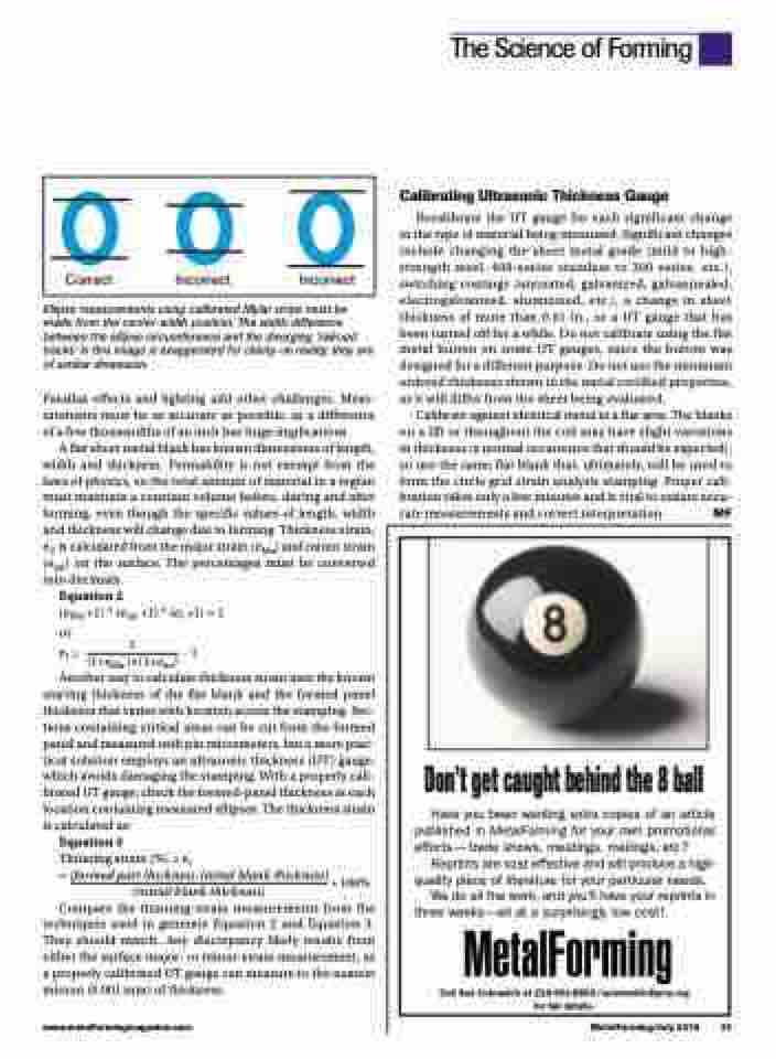
Correct Incorrect Incorrect
Ellipse measurements using calibrated Mylar strips must be made from the center-width position. The width difference between the ellipse circumference and the diverging ‘railroad tracks’ in this image is exaggerated for clarity—in reality, they are of similar dimension.
Parallax effects and lighting add other challenges. Meas- urements must be as accurate as possible, as a difference of a few thousandths of an inch has huge implications.
A flat sheet metal blank has known dimensions of length, width and thickness. Formability is not exempt from the laws of physics, so the total amount of material in a region must maintain a constant volume before, during and after forming, even though the specific values of length, width and thickness will change due to forming. Thickness strain, et, is calculated from the major strain (eMa) and minor strain (emi) on the surface. The percentages must be converted into decimals.
Equation 2
(eMa +1)*(emi +1)*(et +1)=1
or
et= 1 -1 (1+eMa )×(1+emi)
Another way to calculate thickness strain uses the known starting thickness of the flat blank and the formed panel thickness that varies with location across the stamping. Sec- tions containing critical areas can be cut from the formed panel and measured with pin micrometers, but a more prac- tical solution employs an ultrasonic thickness (UT) gauge, which avoids damaging the stamping. With a properly cali- brated UT gauge, check the formed-panel thickness at each location containing measured ellipses. The thickness strain is calculated as:
Equation 3
Thinning strain (%) = et
= (formed part thickness-initial blank thickness) * 100%
(initial blank thickness)
Compare the thinning-strain measurements from the techniques used to generate Equation 2 and Equation 3. They should match. Any discrepancy likely results from either the surface major- or minor-strain measurement, as a properly calibrated UT gauge can measure to the nearest micron (0.001 mm) of thickness.
Calibrating Ultrasonic Thickness Gauge
Recalibrate the UT gauge for each significant change in the type of material being measured. Significant changes include changing the sheet metal grade (mild to high- strength steel, 400-series stainless to 300 series, etc.), switching coatings (uncoated, galvanized, galvannealed, electrogalvanized, aluminized, etc.), a change in sheet thickness of more than 0.01 in., or a UT gauge that has been turned off for a while. Do not calibrate using the flat metal button on some UT gauges, since the button was designed for a different purpose. Do not use the minimum ordered thickness shown in the metal certified properties, as it will differ from the sheet being evaluated.
Calibrate against identical metal in a flat area. The blanks on a lift or throughout the coil may have slight variations in thickness (a normal occurrence that should be expected), so use the same flat blank that, ultimately, will be used to form the circle grid strain analysis stamping. Proper cali- bration takes only a few minutes and is vital to ensure accu- rate measurements and correct interpretation. MF
Don’t get caught behind the 8 ball
Have you been wanting extra copies of an article published in MetalForming for your own promotional efforts—trade shows, meetings, mailings, etc?
Reprints are cost effective and will produce a high- quality piece of literature for your particular needs.
We do all the work, and you’ll have your reprints in three weeks—all at a surprisingly low cost!
Call Sue Cubranich at 216-901-8800/scubranich@pma.org for full details.
www.metalformingmagazine.com
MetalForming/July 2019 37
