
Page 54 - MetalForming February 2013
P. 54
The Science of Forming By Stuart Keeler
Do Higher-Strength Steels Have Less Formability? Part 2
Tooling Technology
Neutral axis
Tension Compression
Tensile test
Do higher strength steels exhibit reduced formability? The most honest answer is: “It depends.” The relationship between yield strength and formability is complex. First, the term formability encompasses widely differing primary forming modes, including tensile stretching, bending and cup drawing. Some modes depend highly on yield strength, while others are completely independent.
Many complex stampings contain all three of the listed forming modes. Interaction and interference among these modes in a single stamping makes failure analysis extremely diffi- cult. Also, formability of several steel types with the same yield strength will vary with different microstructures. What processes were utilized to achieve the given yield strength? Is failure caused by work hardening, inclusions, precipitates, voids or simply grain size?
Last month we showed that failure during simple tensile stretching results from the reduction in sheet thickness due to excessive major and minor stretching in the plane of the sheet. Once sheet thinning reaches the critical value, a local (through-thickness) neck forms that restricts additional deformation within the local neck, creating failure.
The bending mode of deformation
Stuart Keeler (Keeler Technologies LLC) is known worldwide for his discovery of forming limit diagrams, development of circle-grid analysis and implementation of other press-shop analysis
tools. Keeler’s metalform- ing experience includes 24 years at National
Steel Corporation and 12 years at The Budd Com- pany Technical Center, enabling him to bring a very diverse background to this column and to the sem- inars he teaches for PMA.
Keeler Technologies LLC
P.O. Box 283, Grosse Ile, MI 48138
Fax: 734/671-2271, keeltech@comcast.net
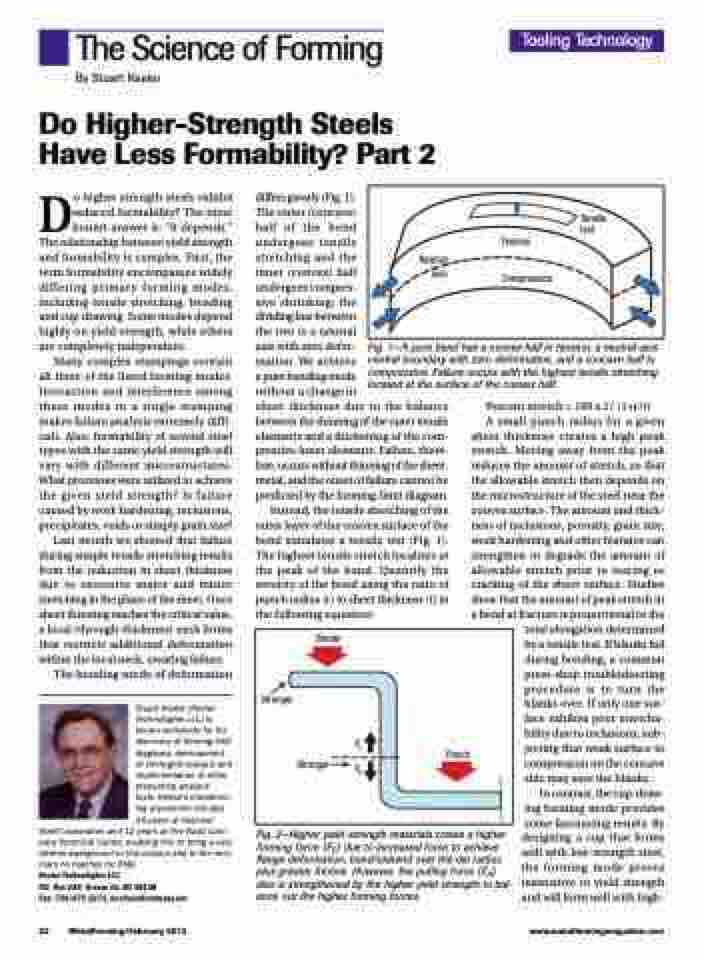
differs greatly (Fig. 1).
The outer (concave)
half of the bend
undergoes tensile
stretching and the
inner (convex) half
undergoes compres-
sive shrinking; the
dividing line between
the two is a neutral
axis with zero defor-
mation. We achieve
a pure bending mode
without a change in
sheet thickness due to the balance between the thinning of the outer tensile elements and a thickening of the com- pressive inner elements. Failure, there- fore, occurs without thinning of the sheet- metal, and the onset of failure cannot be predicted by the forming-limit diagram.
Instead, the tensile stretching of the outer layer of the convex surface of the bend simulates a tensile test (Fig. 1). The highest tensile stretch localizes at the peak of the bend. Quantify the severity of the bend using the ratio of punch radius (r) to sheet thickness (t) in the following equation:
Fig. 1—A pure bend has a convex half in tension, a neutral-axis central boundary with zero deformation, and a concave half in compression. Failure occurs with the highest tensile stretching located at the surface of the convex half.
Percent stretch = 100 x 1/ (1+r/t)
A small punch radius for a given sheet thickness creates a high peak stretch. Moving away from the peak reduces the amount of stretch, so that the allowable stretch then depends on the microstructure of the steel near the convex surface. The amount and thick- ness of inclusions, porosity, grain size, work hardening and other features can strengthen or degrade the amount of allowable stretch prior to tearing or cracking of the sheet surface. Studies show that the amount of peak stretch in a bend at fracture is proportional to the
total elongation determined by a tensile test. If blanks fail during bending, a common press-shop troubleshooting procedure is to turn the blanks over. If only one sur- face exhibits poor stretcha- bility due to inclusions, sub- jecting that weak surface to compression on the concave side may save the blanks.
In contrast, the cup-draw- ing forming mode provides some fascinating results. By
designing a cup that forms well with low-strength steel, the forming mode proves insensitive to yield strength and will form well with high-
Stronger
Stronger
Punch
Binder
FF FP
52 MetalForming/February 2013
www.metalformingmagazine.com
Fig. 2—Higher yield-strength materials create a higher forming force (FF) due to increased force to achieve flange deformation, bend/unbend over the die radius plus greater friction. However, the pulling force (F )
P
also is strengthened by the higher yield strength to bal-
ance out the higher forming forces.
