To overcome insufficient flange width, metalformers can opt for welding electrodes with an offset nose when welding near the edge. Double-bend offset electrodes also provide access to tight weld areas. However, these electrodes exhibit limited weld-force capacity and are expensive. As an alternative, consider investing in an offset or angled electrode holder, which will save money in the long run because it enables use of standard straight tips.
Weld Spacing and Projection Welding
|
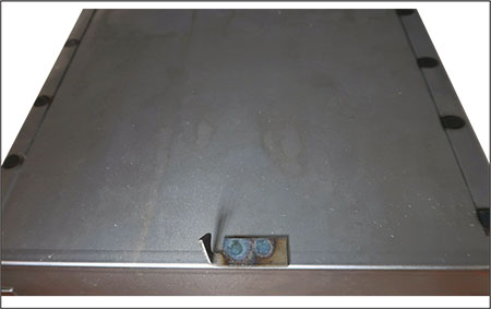
| Here’s an ideal application to convert from spot to projection welding. Welding the small tab causes weld expulsion and weakens the joint. Also, insufficient spot spacing causes the second spot to be weaker than the first due to current shunting. |
Another critical design specification: center-to-center spot-weld spacing. Since electricity always takes the path of least resistance, a second spot weld made too closely to the first will be weak, because part of the weld current shunts through the existing weld. Looking again at the example above (welding 18-gauge mild steel), specs call for a minimum weld spacing of 7⁄8 in.
Where the design calls for tighter weld spacing, consider using projection welding. This resistance-welding process employs projections formed onto one of the parts. The projections, which can have single or multiple embosses of various shapes, concentrate the welding current exactly where the joints need to form. Of all of the resistance-welding processes, projection welding offers the most potential for productivity increases, so metalformers should consider the process even if they must redesign the part and fabricate new tooling.
Many spot-welded sheetmetal assemblies can be projection welded if they already have flanges that will accept the projections. With proper technique, the consistency of joints made by projection welding may greatly exceed that of a typical spot-welding operation.
(Note: If designers have the option to use three or four projections, they should use three for optimum weld-force equalization.)
|
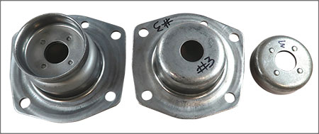
| This projection-welding process employs projections formed onto one of the parts (in this case, the drawn cup to the right). The projections, which can have single or multiple embosses of various shapes, concentrate the welding current exactly where the joints need to form. |
Use a straight-action press-type resistance-welding for projection welding, rather than a rocker-arm machine. In addition, the workpiece material must be strong enough to ensure complete rigidity of the formed projection until reaching the plastic state during the weld sequence, and proper forging of the joint.
The growing popularity of capacitor-discharge resistance-welding machines has opened up projection-welding applications previously considered impossible due to the high secondary amperage required. Some CD welders can produce as much as 1 million secondary amps, enabling resistance welding of parts previously joined using laser welding. However, CD welding requires accurate part and tooling dimensions, and the machine’s force-delivery system must be designed for low inertia and fast follow-up.
Projection vs. Spot Welding
When converting a part originally designed for spot welding to projection welding, production rates can dramatically increase, since the welds formed using several strokes of a spot-welding machine now can form in just one stroke of a projection-welding machine. Also, if required, the projection-welding machine can form closely spaced welds not possible using separate spot-welding tips.
In a typical production run of several thousand parts, imagine how many times the operator would need to stop to dress or change the spot-welding tips, especially when welding coated material. Converting projection welding with flat copper dies equates to having the ideal equivalent of a brand new set of tips for each weld.
An added bonus when using a flat copper die: consistent weld quality throughout the production run, with little to no die wear (if properly water-cooled).
Projection Design
Design guidelines for stamped projections vary with sheetmetal thicknesses. Take care to ensure that the punches used to form the projections do not wear over time and cause inconsistent projection height. Generally speaking, when joining parts of different material thickness, place the projections in the thicker of the two components—greater thickness means more mass and, therefore, a longer weld time to reach the required welding temperature when compared to the thinner component. After completing a properly executed projection weld, the projections should be totally collapsed, with the surfaces of the two pieces in intimate contact and not deformed.
Circular ring projections prove ideal when making air- or liquid-tight welds, such as when welding threaded connections to a water heater or air tank. Switching from arc welding to projection welding for these types of parts will pay big dividends in production speed and weld quality.
Gather additional information at www.rwma.org, the website of the Resistance Welding Manufacturing Alliance, a standing committee of the American Welding Society. MF
Industry-Related Terms: Butt,
Case,
Die,
Edge,
Electrodes,
Flange,
Form,
Laser Welding,
LASER,
Projection Welding,
Run,
Shunting,
Stroke,
ThicknessView Glossary of Metalforming Terms
See also: T. J. Snow Company
Technologies: Welding and Joining


 Tom Snow
 Video
Video