 Andrew Cooke
In Die Fastening, Part One—The Whys and Hows
January 31, 2019Comments
Self-clinching fasteners were developed more than 75 years ago as a method for attaching components to thin sheetmetal and to provide robust connections capable of withstanding axial and torque loads. They are particularly useful where components must be accessed and/or replaced, and where loose fasteners would be inaccessible or where they could pose a risk. Self-clinching fasteners create permanent, reusable load-bearing threads and, once installed, will not loosen or fall out. These attributes make them popular in many market sectors, including automotive where they often are the considered solution for many types of applications, including those categorized as safety-critical.
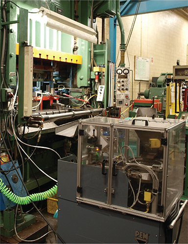 |
| A well-thought-out in-die-fastening system will take into consideration the operating space, tube and electrical routes, and interfaces with the press and press tooling. |
Why Specify Self-Clinch Fasteners?
Given the many benefits that self-clinching hardware can deliver before, during and after production, they are the attachment method of choice for many sheetmetal designers and assemblers for many reasons, including:
- Provides strong reusable threads in thin sheetmetal
- Installs by simple pressing/squeezing of the fastener into uncomplicated pierced holes—chamfering, embossing, etc., is not necessary
- Employs the ductility of the host panel, with the fastener secured by ‘cold-flow’ of the host material—no potentially detrimental thermal stresses are involved, plus the fastener can be prefinished
- Absence of conditions such as weld spatter, which can result in rework or scrap
- Suitable where dissimilar materials are specified, e.g. steel fasteners into aluminium or copper sheet
- Consistent self-clinching performance—reliable pull-through, push-out and torque-out specifications
- Benefits can be enhanced by adoption of in-die-installation technology.
Why Try In-Die Fastening?
|
Options Abound for In-Die Fastener Feeding
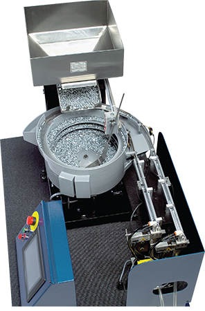
PennEngineering also offers customized PEM feed carts. Designs allow for single or dual bowl carts (pictured) and as many as five feed lines per cart. Multiple carts can be integrated with a die to accommodate more points of installation or a range of fastener types or sizes. |
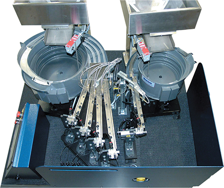 PennEngineering provides two standard designs of PEMserter in-die feed carts: one for use with PEM FH, HFH and HFE studs; and the other for PEM S nuts. Both carts feature as many as four feed lines and both are adjustable to suit fasteners with M5, M6 or M8 thread sizes. These flexible designs enable metalformers to use the feed carts for multiple applications, thus minimizing additional investments on future projects, according to company officials.
In-die fastening can boost productivity when compared to fastener-installation methods that require secondary operations. In most cases, secondary operations run at a much slower rate than the primary stamping process and, as a consequence, the metalformer must build stockpiles of parts from the die, which then sit in queue waiting for fastener-installation processing. In-die-fastening options are available. For example, PennEngineering manufactures both the self-clinching fastener (PEM fastener systems) and the installation equipment (PEMserter).
Such equipment allows fabricators to combine metalforming and fastener installation, thus improving financial and quality metrics. Such improvements include:
- Eliminated work-in-process (WIP) —the stockpiled parts between the primary metal-stamping operation and the secondary fastener-installation process—and its associated costs
- Reduced material handling
- Freed-up WIP storage space
- Improved quality and speedier reaction to quality issues, as well as minimized scrap and associated costs
- Reallocated secondary-process operator
- Improved throughput.
Suitable for Various Applications
In-die installation technology is applied most commonly in progressive- or transfer-die applications. Other applications include tandem press lines, bespoke production lines and for single-station dies where the in-die equipment is used to effect second-operation installation. Metalformers may consider this option when wishing to upgrade the fastener-installation process in a running job without investing in a completely new forming die.