Difficult Welds? Automated Welding May Have an Answer
October 1, 2017Comments
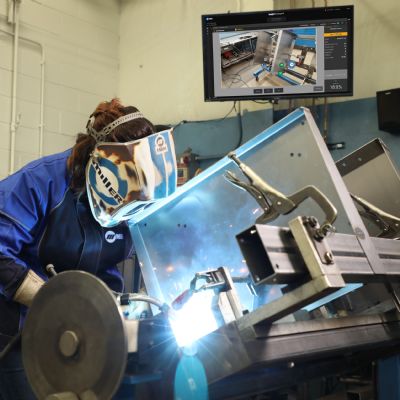
 The efficiencies inherent in automated welding cannot be denied, as the process has proven itself for OEMs and Tier One and Two suppliers alike. But a longstanding challenge remains: automating the welding of materials with irregular, inconsistent or difficult-to-access joint interfaces. Fortunately, advances in sensing technology allow automated welding to tackle such variables and, combined with cost-competitive robotic-welding options, enable automated welding to expand all along the fabricated-part supply chain.
With sensor packages selected, installed and trained (programmed) correctly, the capabilities of robotic arms in combination with controllers are significantly extended. For example, in robotic-welding systems the introduction of sensors provides the adaptive capability of touch and sight to address the challenges of a “moving” weld seam or component. Previously prohibited joint tolerances and configurations now are effectively produced with acceptable quality and weld integrity.
Sensoring has positively addressed inconsistent-joint challenges in these phases of the automated-welding process:
- Joint-edge detection—finding the edge or start of a weld seam
- Joint-seam tracking—maintaining the desired weld path
- Measuring the width or profile of a joint.
For this article, we’ll focus on joint-seam tracking. In some instances the start or edge of the joint may be relatively simple to control within the tooling or fixturing. The seam itself, however, may vary due to manufacturing methodology or thermal influences of the process. Tracking of the seam by various methods can overcome this shortcoming of manufactured parts, offering another opportunity to automate the welding of previously prohibited joints and components.
Three main methodologies can facilitate seam tracking, with each providing varying levels of investment, complexity and capability:
- Vision solutions
- Laser scanning
- Through-the-arc sensors
Historically, most vision applications have been employed in situations where quality requirements were uncompromising, often with significant safety implications. Today sees greater availability of lower-cost and increasingly capable solutions. Consider each system on its own merit, as not all vision/laser solutions offer the same capabilities. 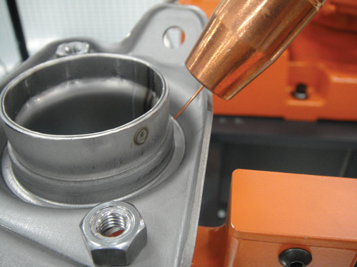
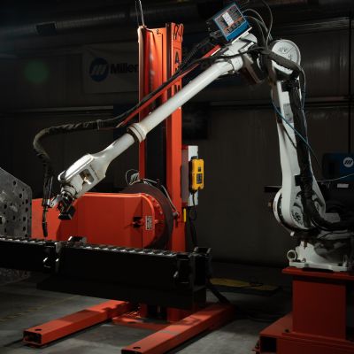
Advancements in sensing technology enables accurate tracking of unique and difficult weld seams, resulting in new opportunities to employ robotic welders.
Laser-scanning technologies fall into the categories of 1D, 2D, 3D, spot, line and circle. All frequently combine with some form of CCD-style camera to capture images for processing with algorithms. Such setups usually are managed by a host PC (often combined with the camera as a space saver) that calculates the input data and produces the necessary output for the robot to execute its task.
To ensure the effective deployment of vision/laser solutions, ask the following:
- When sizing up the task, what is the smallest object or feature to be tracked/detected?
- When viewing the feature or part, what level of measurement accuracy is required to meet the process criteria?
- What size of field of view is required to capture essential information when tracking?
- What is the speed of recognition and processing time required to meet output-cycle requirements?
When selecting the right laser/camera combination, consider environmental aspects. Temperature, vibration, illumination and humidity all can affect the quality and reliability of results. Note that some cameras are best suited for static capture and others perform better for linear tracking.
The combination of process-head and component geometry also may dictate what size lens and camera arrangement can be installed on the end of the robot arm. Time spent with quality 3D-simulation software is very important. Simulating the movement of the robot and its end-of-arm-tooling minimizes risk by thoroughly identifying what welds can be accessed, as well as any potential compromises that may arise with certain camera/lens configurations. Beyond the physical constraints, determine whether your company has the expertise to configure the equipment, and the level of the support that’s needed for system startup and operation.
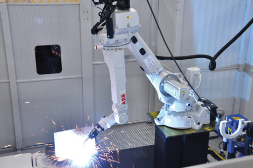
Seam-Tracking Technology Propels Automated Welding
When looking to track the seam and/or volume-fill a continually changing joint configuration, vision and laser are not ideal tracking methods. Instead, a through-the-arc approach may mean the difference between producing a repeatable, quality joint via automation, or completely abandoning the automation option altogether.
Through-the-arc-tracking has evolved considerably in recent years, with reliable, fast and accurate tracking of a weld joint becoming second nature to a robot. In practice, through-the-arc sensing monitors the arc in order to track the seam, using impedance—resistance to an electrical circuit—rather than simple volts or amps. Doing so provides more reliable values for producing accurate data. 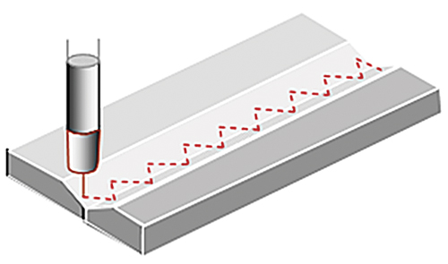
Through-the-arc seam tracking works by measuring the impedance of the arc as the weld wire is directed over a seam in a weave pattern, as illustrated here. A variety of weave patterns can be employed based on the type of seam and other factors.
ABB’s WeldGuide III software provides an example of how seam tracking works. It operates by introducing a weave pattern, which is freely programmable in time, geometry, symmetry and amplitude. The robot controller library also holds a default set of weave patterns. Actual tracking of the joint is achieved by monitoring the impedance of the arc as the weld wire weaves from side to side, and the rules of the chosen or programmed weave data determine how the robot reacts. The changing impedance is used to modify, in real-time, the wire-feed speed (amps and fill ratio) and robot travel speed. This combination of attributes greatly increases the variety of workable joints and materials.
Seam tracking requires no external apparatus to execute its tasks, providing a viable option for joint types with access challenges that have previously precluded the use of bolt-on equipment. And, in simple economics, the capital investment of through-the-arc sensing can be as little as 10 percent of a comparable vision or laser solution.
A top-performing through-the-arc seam tracking setup provides the combined benefits of economics, technical capability and physical geometry. While the ratio of investment to capability for this type of seam tracking solution has been well established over the years, recent process advancements have continued to push the boundaries of capability in addressing the problems of the ever-changing joint configuration.