Peter Ulintz Peter Ulintz
Technical Director

Forming Aluminum Stampings—Part 2

May 1, 2009
0
Comments


Remove the sides of a square or rectangular box and the remaining corner radii could be assembled into a cup. Consequently, the box corners form in a manner similar to cup drawing, where the corners are compressive on the material moving toward the die radius and tensile on the material that has been drawn over the radius. Material flow in the sides and ends of the box is bending and straightening.

Aluminum products can be particularly difficult to form due to serious wrinkling and tearing problems associated with their lower forming limits. Because different forming modes and complex material flow are required to produce the corners and side walls, several important factors must be considered when forming aluminum parts.

Blank Shape and Blankholder Force

Rectangular blanks often are chosen for simplicity and low cost. While this shape simplifies the manufacturing process, it does not maximize formability. Compared to steel, aluminum-alloy sheet has reduced stiffness and much less stretching capability. As a result, the shape of aluminum blanks must be optimized to minimize buckling and stretching tendencies. A final blank shape usually is developed using analytical methods such as metalforming simulations or by trial and error. Regardless of the chosen method, developed blanks will vastly improve aluminum draw-forming processes.

Draw pads (blankholders) and nitrogen-gas springs are routinely employed to provide economical blankholding pressure. A disadvantage with this arrangement is that blankholding pressure increases with punch travel (depth of draw) because the nitrogen gas cylinders are being compressed. The rise in pressure occurs at a time when the blank area under the draw pad is being reduced.

Applying increased pressure to a decreased flange area acts to restrict material flow into the die cavity, which in turn causes the sheetmetal to stretch. Combined with aluminum’s limited stretching capabilities, the maximum achievable depth of draw is effectively reduced. A more desirable blankholder-force profile is one that decreases in pressure as the blank area is reduced. Such pressure profiles can be achieved using programmable hydraulic pressure systems or other recently developed variable-blankholder technologies.

Additional clearance and spotting for improved material flow.
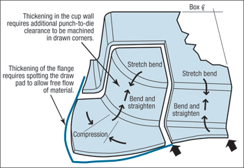
Fig. 1—Additional clearance and spotting for improved material flow.

As mentioned, the corners of a box form in a manner similar to cup drawing. This includes material thickening found in the vertical cup wall and the flange remaining on the blankholder. Allowances for thickening must be provided in the draw corners by machining additional punch-to-die clearance in the vertical wall and spotting additional in the blankholder (Fig. 1).

Spotting consists of locally grinding specific areas on the blankholder to account for nonuniform thickening in the corner flange area to help improve material flow into the cavity. This is usually done by trial and error. Spotting can sometimes be avoided when drawing low-carbon steel or other highly formable materials by using gap blocks or standoffs on the blankholder. However, spotting is particularly important when working with aluminum alloys because of their tendency to wrinkle and buckle. Spotting increases the contact area and force distribution across the entire blank surface.

Product Geometry

Aluminum-sheet forming depends highly on the part design, including radii, draw depths, wall angles, steps and transitions. These variables interact to affect the cost and quality of the aluminum stamping. The size of the plan-view corner radius in a box, for instance, has a strong influence on the maximum depth of draw. As a general rule, increasing the plan view corner radius reduces forming severity at the draw corner because there is a larger area for the material to be compressed. A small plan-view radius reduces the area in which the material can compress. This significantly increases forming severity in the corner, thereby reducing the maximum depth of draw.

Increasing the length-to-width ratio of a rectangular box also will decrease local forming severity. The increase in aspect ratio allows the blank to draw in faster on the long side as compared to the corner. The difference in material flow rates allows material from the corner to flow laterally into the side wall; thus, providing a corner-assist effect.

Part radii specifications should be selected carefully. Small radii can restrict material flow, localize strains and substantially increase drawing loads. Large die radii reduce bending and straightening forces, thus easing the draw. However, overly large radii will decrease the blank contact area between the die radius and the punch face, increasing the tendency to form wrinkles in this unsupported region. As a general rule, punch and die radii for aluminum will be in the range of eight to 10 times material thickness on the punch and five to 10 times material thickness for the die. Keep punch radii equal to or greater than the die radius to reduce the likelihood of the punch breaking through the material.

Addendum features added on beyond the product trim line.
Fig. 2—Addendum features added on beyond the product trim line.
Difficult and irregularly shaped product geometries often require the use of addendum to improve material flow. Commonly used addendum features include draw walls, draw bars, material gainers, take-up beads, pillows and punch extensions. Addendum features are added beyond the product trim line (Fig. 2) to assist material flow by balancing cross-sectional lengths of line and providing a constant depth of draw.

Designing draw-die addendum is not a simple task and is too complex to address in detail here. However, when addendum is required it is extremely important that it be designed correctly. Since aluminum is expensive and addendum (which means to add on) requires additional trim material that ends up in the scrap container, shortcuts inevitably occur for the sake of material conservation. Avoid this temptation no matter how much pressure is applied by others to keep material consumption within budget. Nothing short of a total redesign can compensate for a draw die with poorly engineered addendum. When a new die with proper addendum design is built, the added material cost will pale in comparison to the die maintenance, press downtime and expedited shipping costs incurred with alternative designs that supposedly save money on material costs. MF

Industry-Related Terms: Alloys, Bending, Blank, Compress, Corner Radius, Corner, Die, Draw, Drawing, Flange, Form, Forming, Grinding, Scrap, Surface, Thickness, Wrinkling
View Glossary of Metalforming Terms

Technologies: Materials, Tooling

Comments

Must be logged in to post a comment.
There are no comments posted.

Subscribe to the Newsletter

Start receiving newsletters.