Peter Ulintz
Redrawing Square and Rectangular Box Shells
December 1, 2019Comments
At a recent seminar, as in past columns, I addressed deep drawing of square and rectangular box shells. Based on the resulting questions and discussions, it has become apparent that a technical column on redrawing square and rectangular shells might be beneficial.
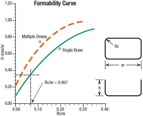 |
| Fig. 1—Draw reduction graph for box shells |
Determining the Required Number of Draws
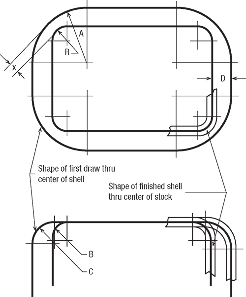
In determining the maximum depth of a drawn (in one operation) square or rectangular box shell, the size of the corner radius is the main factor, with radius of the drawn part always specified to the centerline of stock (the midpoint of material thickness).
In general, square box shells can be drawn from a flat blank to a depth equal to about 80 percent of their width with a relatively small corner radius. Rectangular box shells can be drawn to greater depths than square boxes. The depth of draw increases with the increasing width of the longest side. The formability diagram in Fig. 1 illustrates the relationship between the maximum depth of draw (h-max), the width of the longest side (w) and the size of the corner radius (Rc) on the number of draws required for a rectangular product.
More specifically, a box shell with a corner radius between 3⁄8 and 1⁄2 in. may have a depth of draw of six times its corner radius, while a box shell with a corner radius exceeding 1⁄2 in. generally has a depth of draw of four to five times the corner radii. In both cases, the distance between the centers of the corner radii must be greater than, or equal to, six times the corner radii. If less, the shell’s depth of draw decreases proportionately.
Determining Redraw Die Parameters
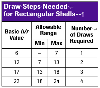 When the allowable depth of draw is shallower than finished-product requirements, the process requires a redraw operation. The accompanying table from J.W. Lengbridge, Theory and Practice of Pressing Aluminum serves as a guide for assessing the necessary number of draw steps to produce rectangular shells, based on the ratio of the wall height to the corner radius (h/r). Though developed for aluminum, I find that the table also works well for steel.
The amount of reduction between redraws depends on the corner radius, which shrinks incrementally with each reduction. When two or more reductions are required, take these steps to determine the length and width of each shell:
- Starting with the finished part geometry, multiply the corner radius by 3.
- Multiply using a constant of 0.75 on corner radii greater than 1/2 in., regardless of the corner size.
- Add the product for the calculation above to the current length and width, which will be the length and width of the preceding draw shell.