 “Using automated process programming in the CAM software,” Rooks adds, “we can take a known process and use it to program subsequent parts. We can capture and color-map the surfaces that the user is depositing onto and automatically apply the correct DED tool paths so that there’s less intervention from the CAM programmer. The end user then has a programmed part and established process with a known baseline. Then, when there are similarities in geometry of subsequent DED jobs, based on the way the CAD is presented we can leverage automated features in the software to program those new features with just a few mouse clicks.”
“The process has to be similar,” Levine says. “The automation works by adjusting the geometry but it’s the build process that we’re replicating.”
Relatively Unlimited Geometry
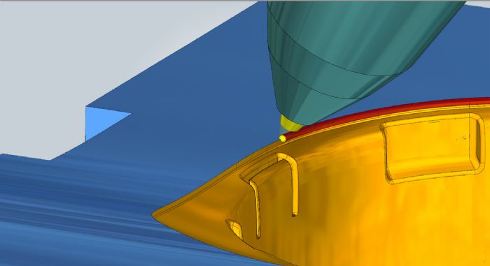
 One advantage of the DED process compared to powder bed: no need for support structures. “With DED on a CNC machine, we can articulate the axes to stay perpendicular to the build and avoid the need for supports,” Rooks explains. “Automation—of both the process and programming—then contributes to the overall efficiency of the DED process.”
“With new CAD-CAM software such as hyperMill,” says Levine, “programming is highly flexible so that almost any traditional machining process can be referenced for an additive DED process. Then, its broad flexibility also addresses some of the challenges related to the types of parts made. We see DED being relatively unlimited in the types of geometries that can be built, and being simpler to adopt for a new user compared to other metal-AM processes. The market will grow as more companies realize this. We see the process being used to coat some really dynamic surfaces that you wouldn’t be able to work on without these developed machine-control capabilities.”
While Levine and Rooks both note that the DED process often starts with a simple substrate—a plate for example—it then allows users to build up sections and final-machine them to precise dimensional specs.
“For example, with plastic injection molds,” Rooks says, “we can refurbish by milling off a reference layer of material to provide the base geometry for the CAD-CAM software, and then use that CAD model as the reference surface to program a new buildup with the DED process.
“We’re also hearing about some relatively new applications for DED,” Rooks continues, “relating to battery-cell technology. DED allows for the blending of materials that comprise the inner structures of a battery cell. The process can precisely interleave these materials, fully blended or layered with gradient values established by the programmer.”
Building Rotationally Symmetrical Geometries
When it comes to hyperMill CAD-CAM software supporting the DED process, all of the basics for the process are built into the software, explains Rooks, such as rotating start-stop points around the build, how the build differentiates from peripheral to infill, and moving back and forth to fill in.
“We’re also pushing new ideas,” he says, “such as building rotationally symmetrical geometries, even with variable thickness. Traditionally, building these geometries requires numerous starts and stops, which can lead to discontinuities in the build. We recently developed an additive turning process where you essentially take a 2D slice and set the tool-axis orientation so that during post processing it becomes a true five-axis tool path. This keeps all of the tool-axis articulation to the vectors established in that 2D slice. This way, as the build progresses, even if it’s very complex, there’s only one start point and one stop. This avoids creating the discontinuities you would otherwise have within the build.”
“When you’re processing the pre-posted code and actually mapping it to the kinematics of the machine and you pass through the pole,” Levine adds, “the C-axis will whip around to keep it on one side of the rotary. We can program around that so that the secondary rotary will just position and transition through, rather than having that C-axis motion come around to the point.”
The result: The DED machine runs better, Levine and Rooks say. “If you have those constant motions where you hit the pole, all of the geometry is pulled around and whips fast, and you lose the real traverse speed of the AM head,” Rooks explains. “This is what causes overbuilds and underbuilds; the head is not traversing at its true standard rate and staying constant. By getting around that C-axis polar move, we can pivot all of the way through the raised rotary without having the whip-around move.”
Hybrid-Machine Advantages
Levine and Rooks also point to the advantages of applying the DED process in a hybrid machine, where subtractive and additive manufacturing occur in one environment. To illustrate, consider building a part surface using AM by depositing five 1-mm layers.
“In the end, the final buildup will not be 5 mm; the process isn’t perfect,” Levine says. “When the process moves out of control, the ability to go back and machine the deposited material and then requalify the top surface—it may be 4.5 mm high, for example, after the five passes—allows us to then continue the process knowing exactly where we’re at, 4.5 mm rather than 5 mm. All of this affects build quality as the passes build up, because the laser focal position changes from optimal if you don’t account for that precision with each pass. If laser position is not in control, build quality will suffer.”
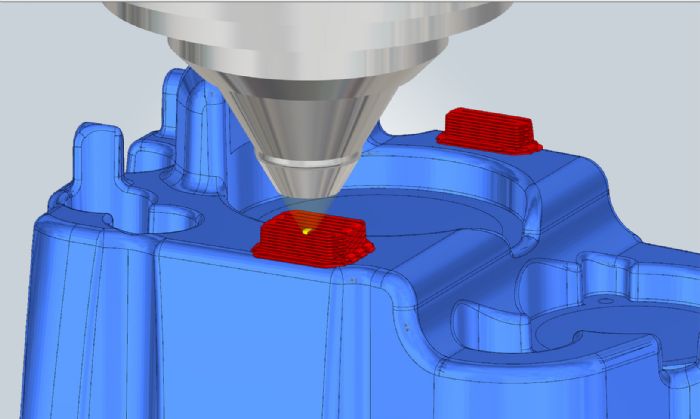
Also important is the ability to control the process parameters specifically for different areas of the build. “This is a relatively new capability developed in response to customer feedback,” Rooks explains. “For example, when running a hybrid machine tool for DED and we need to turn a sharp corner, one of the common problems is that the machine tool must slow down in the corners and then accelerate out. This leads to uneven builds in the corners. A new software feature provides process-parameter control so that when navigating corners, we can program the DED process parameters to prevent these overbuilds in user-defined build zones.”
Here, full five-axis motion control becomes critical. “Machine-motion smoothness is paramount,” says Levine, “otherwise, with the rate of traverse of the head especially with rotaries in play, process consistency suffers. So, good five-axis motion control is critical to optimize results.”
Another example where five-axis motion pays off: polar moves or dwells. “In the subtractive mode you might just get a little witness mark on the part,” says Rooks. “But with AM, that dwell leads to overbuilds. Again, smooth motion is critical during the DED AM process.” 3DMP
Industry-Related Terms: Alloys,
Bed,
CAD,
Cam,
CNC,
Coat,
Corner,
LASER,
Layer,
Model,
Plate,
Point,
Surface,
ThicknessView Glossary of Metalforming Terms
See also: Open Mind Software Technologies, Inc.
Technologies:


 Brad Kuvin
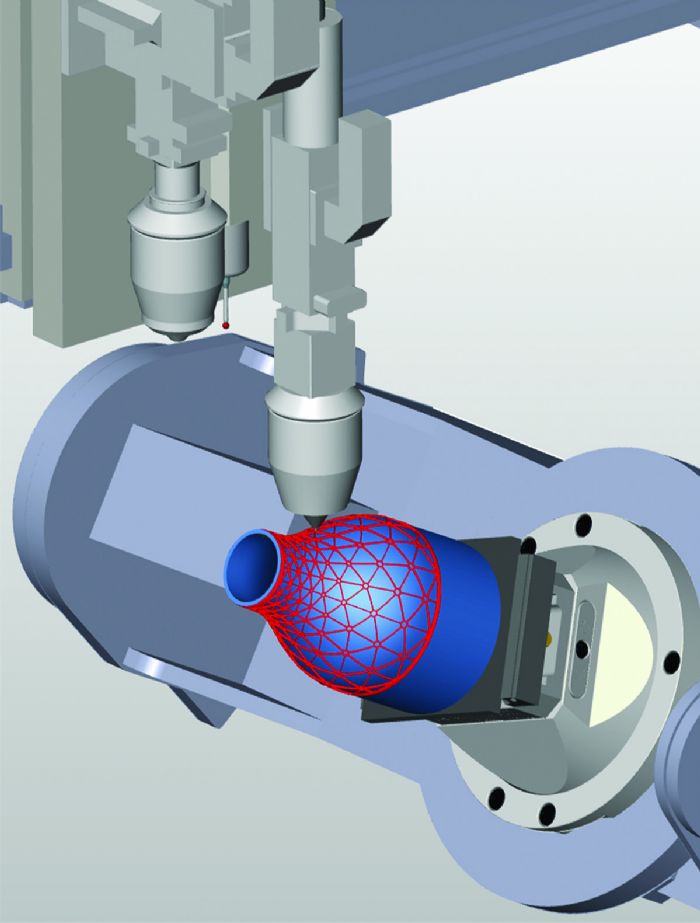 DED processes find use for fabricating primarily large parts; repairing worn or deteriorated parts; adding new features to existing parts; applying metal coatings; and creating new materials from multiple metal alloys. DED setups comprise a device to feed the printed material (powder or wire); an energy source (laser, electron beam or electric arc) to melt the metal; and a manipulator (gantry or robot, for example) to direct the molten metal to the build.
 Video
Video