Maximizing Your Laser's Productivity
November 1, 2012Comments
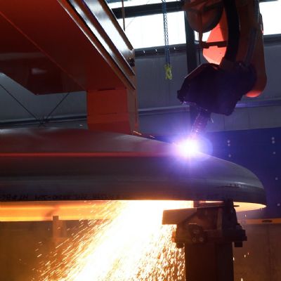
During the last two decades, lasers have become a critical tool to help manufacturers deal with a rapidly evolving environment, one that has driven the metalforming and fabricating industry to new levels of lean and efficient production. State-of-the-art laser-cutting machines optimize efficiency by eliminating multiple setups required with other processes.
That efficiency optimization took a leap forward with the recent advent of automatic changeout of nozzles and cutting lenses, as well as the ability to detect when there is a problem with either the nozzle or lens and adjust the cutting program accordingly. Metalformers can leverage these recent advances to turn a maximum lot size of a single part into a profitable endeavor, by eliminating setups and increasing the machine’s green-light on-time (GLO).
Extracting Flexibility
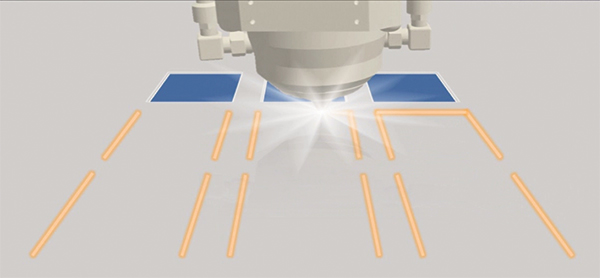 |
| Fig. 1—During flash cutting, the laser beam cuts all of the lines of a grid pattern on the sheet in one direction, then cuts all of the lines running 90 deg. to the initial cuts. |
This article could go on and on about how lasers improve efficiency and promote lean concepts, while improving quality, but that’s just part of what lasers can do. It’s more about extracting the flexibility that a laser beam inherently possesses.
The laser has been called the “ultimate soft tool,” due to its ability to adjust to the changing demands placed upon it. By tapping into some of the deeper application advantages of a laser, not only can metalformers achieve better cut quality and faster turnaround, but they also can reduce process time for downstream activities such as bending, parts cleanup and separation.
When you hear the term “applications,” you may think of cut conditions. This is common terminology used when fine-tuning cutting speeds, power and gas output to produce acceptable edge quality at the fastest rate possible. However, true applications go beyond that into improving process times, and even developing techniques to streamline other processes—value-added or nonvalue-added.
In this article we focus on two such techniques possible with some—not all—laser-cutting systems. They are based on the ability to create a beam with a fine spot size, and to precisely control the beam power output to, in the end, produce high-quality parts in an incredibly short amount of time.
Note: Some applications for the technology described here are only possible on cutting machines equipped with certain types of drive systems or with certain CNC controllers.
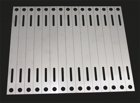 |
| Fig. 2—Chain cutting creates several parts tabbed together on a sheet. This eliminates the possibility of the parts tipping up and causing a cutting-head crash. |
Flash Cutting
Flash cutting (as Amada refers to it) is a technique used when cutting grid patterns of squares or rectangles from a nested sheet. Historically, when laser cutting a square or rectangle a metalformer would pierce the center of the contour, or pierce closer to the edge, and then lead-in to cut the shape. During lead-in cutting, cutting speed slows as the beam approaches each corner, and then accelerates to the established cut speed to complete each side of the four-sided shape.
While this process suffices and still finds use, a better method has recently been introduced to metalformers to provide a faster to complete a grid pattern (Fig. 1). The key is optimum synchronization of the oscillator, CNC control and motion system. Using this flash-cutting technique, we start with a pierce directly on the line (with cutter compensation, of course), eliminating a lead-in. The beam cuts all of the lines of the grid pattern in one direction, and then cuts all of the lines running 90 deg. to the initial cuts. Operating at high speed, the laser beam begins precisely at the corner of the square or rectangle, and then shuts off precisely at the opposite corner. As the cutting head continues toward the next rectangle, the beam again turns on precisely as it reaches the coordinates for that next corner. The process repeats back and forth until all of the parallel lines in one direction have been cut, and then the laser repeats that process to make the perpendicular set of cuts.
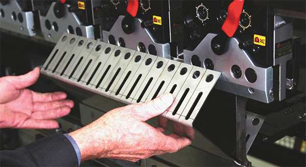 |
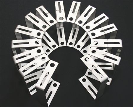
| Fig. 3—Chain-tabbed sheets can allow a metalformer to gang-bend all of the parts simultaneously in a press brake, which can be a huge time saver when bending large quantities of small parts. |
Flash cutting proves ideal for processing thin materials where no pierce routine is required. Machines equipped with linear drives will provide the highest degree of accuracy while optimizing cutting speed and part quality. By using higher accelerations (to 5G typically), this process has proven to improve process time by as much as 500 percent over conventional cutting techniques.
Chain Cutting
Chain cutting allows metalformers to tab several parts together on a sheet, created by cutting all of the parts with one common outside cut (Fig. 2). Several advantages arise with this process, often used to cut relatively small parts. Typically when laser cutting of small parts, if the parts are not tabbed into the sheet they will either fall through onto a conveyor or collection bin. However, if they fail to properly release from the sheet, the parts may tip up and potentially cause a hazard—an opportunity for a cutting-head crash. While in some applications it may be acceptable to allow parts to fall through the sheet, this practice requires added operator time to retrieve the parts from a bin also containing slugs and dust. Additionally, while laser tabs work well in some situations, when the operator removes the sheet from the cutting table he must break each individual part out of the sheet skeleton.
A better solution: The chain-tab technique. Here a group of parts can easily and quickly be removed from the skeleton all at once, instead of as individual parts. Metalformers opting to employ the chain-cutting technique find that they can rapidly remove parts from the pallet and load a new sheet on. They also enjoy quick and easy separation of the parts once they are removed from the skeleton, while also generating less laser dust and spatter that might otherwise require a secondary cleaning process.
 |
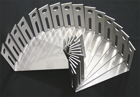 |
| Figs. 4-5—After gang-bending small parts that have been chain-cut, an operator simply separates the individual tabbed parts from the blank. | |
We’re also seeing some metalformers employing automated part separation from the skeleton while using the chain-tabbing technique. One method to automate part separation is the use of suction cups on an articulating mechanism, such as a robotic arm or moving gantry system. While cutting of small parts has als been an automation challenge, by chain tabbing multiple parts together we can create a unified part large enough for suction cups to attach and remove from the skeleton.
Cut Together, Formed Together
Last but not least, chain-tabbed sheets can allow a metalformer to gang-bend all of the parts simultaneously in a press brake (Fig. 3). Obviously this can be a huge time saver when bending large quantities of small parts requiring one or two bends. After bending, the operator simply separates the individual tabbed parts from the blank (Figs. 4-5).
In the example shown, rather than making 30 bends in the press brake to form the 15 parts, only two strokes of the press-brake ram are required. MFView Glossary of Metalforming Terms
See also: Amada North America, Inc
Technologies: Bending, Cutting, Fabrication