Four Cures for Sheetmetal-Shearing Defects
March 1, 2018 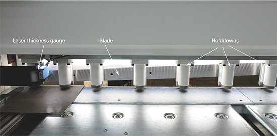 During the early stages of a sheetmetal-fabrication process, shears often get the call for cutting straight lines on sheetmetal and plate. Here, blankholders clamp the edges of the material while two opposed cutting tools perform the shearing action. During the shearing process, a moving blade descends across a fixed blade, with the gap between them determined by a required offset.
The machine oeprator can set the moving blade at an angle (typically called the shearing or raking angle) to shear the material progressively from one side to the other. As rake angle increases, the amount of force required decreases, and stroke increases.
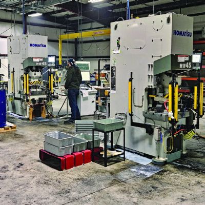
Equipment-wise, the shearing machine (above, and Fig. 1) comprises a shear table, blankholders (F), upper and lower blades (A, E), and a backgauge (G), used to ensure that the workpiece is being cut in the proper location. Additional equipment can incude a back support, used to support the sheared part, as well as optional automatic unloading or stacking apparatus.
Achieving perfect cuts starts with using a high-quality shear equipped to minimize the effects of variable sheetmetal properties, including internal
stresses and geometry. These natural effects, if not corrected and compensated for, become defects in the final product, reducing their quality.
Variables in the Shearing Process
|
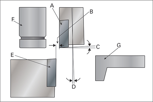
| Fig. 1—A typical shearing setup includes a shear table, blankholders (F), upper and lower blades (A, E) and backgauge (G). B represents blade clearance; C, the angle of the blade cutting edge; and D, the clearing angle (which facilitates part removal). |
|
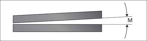
| Fig. 2—Shearing angle (M), less than 3 deg., impacts shearing force and the tendency of the workpiece to twist. |
|
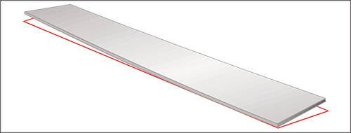
| Fig. 3—To reduce twisting (shown here), fabricators shold reduce rake angle and blade speed. Adding an antitwist device also proves useful. |
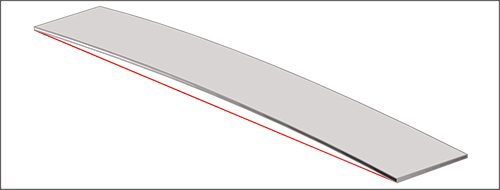
|
| Fig. 4—To reduce crooking (shown here), fabricators should reduce the shearing angle and perform precuts along the rolling direction. |
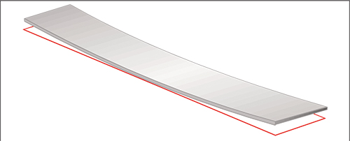
|
| Fig. 5—Reduce bowing by reducing the shearing angle and using a back support to hold the workpiece. |
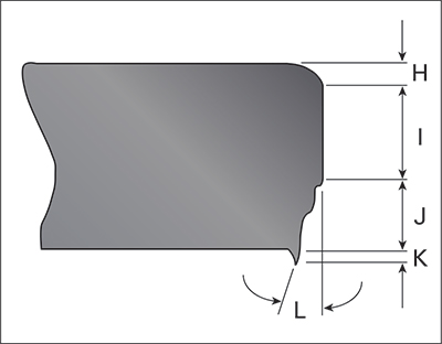
|
| Fig. 6—How shearing affects the workpeice material: H represents the region of plastic deformation; I, the clean zone (neat and regular cutting); J, the fracture zone; K, edge burr; and L, the angle of the fracture zone. |
Cutting angle (C in Fig. 1) represents the angle of the blade’s cutting edge. It influences the shearing force: Using two square-edged blades requires a higher cutting force than if the upper blade is ground at a slight angle, usually to a maximum of 87 deg. The lower blade always sits at 90 deg.
Fabricators often use four-edged blades (90-deg. blades), which allows them to turn the blades, and use all four edges for shearing. Angled blades, called two-edge blades, allow use of only two cutting edges—the opposite edges have an angle greater than 90 deg. and therefore cannot be used for shearing.
Shearing angle (M, Fig. 2), less than 3 deg., has a great effect on shearing force and an important effect on twisting, which can occur when shearing thin strips.
Blade clearance, a key factor in ensuring good edge quality, represents the perpendicular distance (B in Fig. 1) between the shearing blades. The exact cutting clearance depends on workpiece thickness and material strength. Insufficient cutting clearance leads to increased tool wear and tooling costs, and cutting force will rise. Excessive cutting clearance causes the workpiece material to draw between the two blades—the cut edge will exhibit increased taper and excessive plastic deformation.
As a rule of thumb, for shearing mild steel to 10 mm thick, set blade clearance to 0.06 mm per mm of workpiece-material thickness. For work thicker than 10 mm, set blade clearance to 0.04 mm per mm of plate thickness. In Imperial units, set blade clearance to 0.06 in. per each in. of material to 1 in. thick, and to 0.04 in. per in. of plate thickness for work thicker than 1 in.
For example, to cut 16-mm-thick plate, set blade clearance to 0.64 mm (0.04 x 16). In Imperial units, shear ½-in.-thick plate with a blade clearance of 0.03 in. (0.06 in. x 0.5).
Clearing angle (D in Fig. 1), which represents the tilt of the blade ram toward the back of the shear, facilitates part separation. Most applications call for a 1.5-deg. clearing angle.
A Quartet of Common Shearing Defects
Common shearing defects include torsion, straightness error (crooking), bowing, and poor edge quality.
Twisting (Fig. 3)
Here the blade twists the plate along its axis. This typically occurs when shearing narrow strips (less than 10 times material thickness). Shearing conditions that increase this defect relate to workpiece geometry (excessively thick work, reduced width and short length), material characteristics (soft material or uneven stress distribution) and cutting parameters (high rake angle, high cutting speed).
To reduce this defect, fabricators opt to lower the rake angle and blade speed. It also proves useful to add an antitwist device—a series of hydraulic cylinders that push the plate against the top blade, providing an opposing force during shearing that is proportional to the workpiece thickness.


 Coil and Sheet Handling