Brad Kuvin Brad Kuvin
Editorial Director

High-Pressure Lube System Solves Deep-Draw Challenge

March 1, 2012
0
Comments


This is a story of true cooperation and teamwork among several suppliers, leading to a successful outcome for a uniquely challenging metalforming application. The task: Engineer a process to deep-draw compressor shells in a mechanical press, while avoiding the need for secondary operations. The customer: Bettcher Manufacturing LLC, Reynosa, Mexico, deep-draw specialists serving primarily the HVAC market. The plant operates hydraulic and mechanical presses rated to 900 tons.

Operators at the Bliss 900-ton press feed blanks into an idle station in the seven-station transfer die, which consumes nearly every cubic inch of available press space. The transfer station lifts up and out of the when Bettcher needs to run the press in the progressive-die mode, using a stationary coil-feed line (far right).
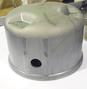
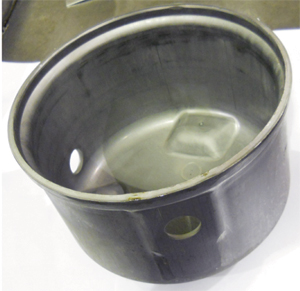
Early in 2011, Bettcher tooling-project engineer Gary James faced the challenge of engineering a process to deep-draw two families of parts for a compressor shell. Upper shells are of 0.155-in.-thick steel with draw height ranging from 6.5 to 8.5 in.; bottom shells are of 0.215-in. steel, with a 7-in. draw height. While Bettcher could easily have formed these parts in any of its hydraulic presses, doing so would have required secondary operations; it sought to run the parts from blank to complete, with holes and forms, in one operation. 
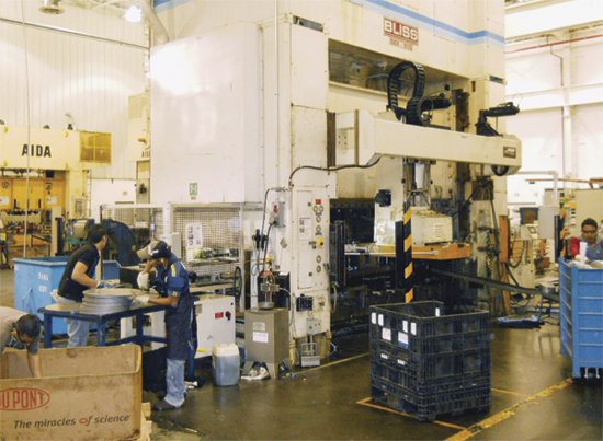
Says James: “We opted to have a transfer die designed and built to run the jobs. And, after reviewing the size of the parts and depth of the draws, we knew the job would take every ounce of capacity from our largest mechanical press, a 900-ton straightside.”

One Heavy-Duty Lube

To run the job in a mechanical press, James and his team also knew that the lubricant and lubricant-application system would hold the keys to the success of the project. And with part volumes of around 1 million per year for one of Bettcher’s primary customers, failure was not an option. The customer had given James and his team six months to move the job from development through to production.

“To run the shells on our big-bed mechanical press (a Bliss 900-ton straightside),” says James, “we knew we had to use the most viscous lube we could find.” The lubricant of choice is a 2000-SUS viscosity heavy oil delivered straight from a 30-gal. reservoir at the press. To provide a system to move the oil from the reservoir to several nozzles stationed in the die, Bettcher turned to Pax Products, which developed a custom lubricant-delivery system built from stock components. 


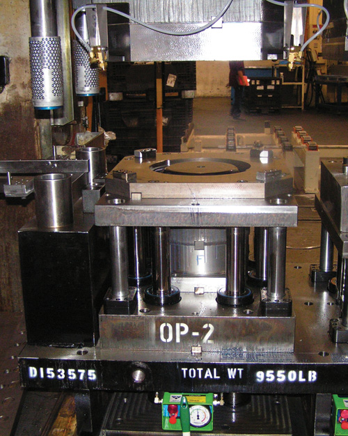
The process calls for deep drawing in the second and third die stations (the first station is an idle). Flanges are then flattened, trimmed and wiped, and holes pierced. The high viscosity of the draw lubricant, combined with the limited space available in the die, required use of four high-pressure piston spray nozzles to obtain full coverage at the two draw stations (shown here).

Spraying the lubricant directly inside the die ensures placement of the lube exactly where it’s needed, when it’s needed, says James. And, using the Pax airless-spray system, there’s no concern with atomization and mist. The lube adheres well to the workpiece material and to the tooling, ultimately minimizing lubricant consumption compared to alternative methods. 

A Special Die, with a Special Tool Coating

James describes the seven-station transfer die, designed and built for drawing the compressor shells by Walker Tool & Die, Grand Rapids, MI. “We’re drawing in the second and third die stations (the first station is an idle),” says James. “Then we flatten and trim the flange, wipe the flange down and pierce holes in subsequent stations. The two draw stations and flanging stations are most critical, where we absolutely must have dependable, repeatable lubricant application.” 

Walker built the 24,000-lb. die in two sections, married at the press using subplates and a Dutchman connection. All of the die’s electrical, air and lube lines interconnect so that only one line for each service connects to the press control.

Working in concert with the lube is a special PVD tool coating provided to Walker by Richter Precision, which applied its newest-generation coating, called Titankote C2SL+S, to components at critical die stations. As described by Richter, the coating process uses ion implantation to impart titanium atoms into the surface of the tools, followed by the deposition of hundreds of alternating layers of AlTiN and CrN. Then, a dry-film lubricant (molybdenum-tungsten-disulfide) is applied and embedded into the surface of the PVD coating, for a final coating thickness as great as 10 microns.

Fully Pressurized Lube System

To consistently and reliably deliver lubricant to the die and onto the workpiece, Walker integrated a Pax fully pressurized delivery system featuring the firm’s new high-pressure piston nozzles. These nozzles, according to Pax sales and marketing manager Pat Ontrop, can apply the lubricant at an increased pressure without the need for a larger pump or increased air pressure. 

“The nozzles can easily be retrofitted into existing Pax prepressurized systems if needed, to spray thicker lubricants,” adds Ontrop.

Lubricant is prepressurized from the reservoir tank at the press to individual, distribution piston pumps mounted in the die. Each pump feeds a nozzle attached to the bottom of the upper die; a digital timer controls nozzle cycling and a filter-regulator-lubricator unit provides regulated, lubricated air to the pumps. The lubrication system is connected to the press control to trigger a press shutdown should the lubricant reservoir run low.

For the retrofit, Bettcher had to specify larger-diameter lubricant-delivery lines than are typically used, and also locate the distribution pumps particularly close to the tooling. “Twenty-foot lines wouldn’t suffice here,” says Ontrop. “For these high-pressure systems, to move more viscous lubricants we typically would keep line length to 8 ft. or less. Here the lines are 4 to 5 ft. long.” 

While Walker originally planned for three nozzles per draw station, it found that four per station were needed to obtain adequate coverage in the draw stations; two nozzles suffice in the flanging operation. The system can cycle each line as quickly as 300 cycles/ min., and with each cycle can apply as much as 0.2 oz. of lubricant per line.

The Bliss press has an 18-in. stroke; the die, which consumes nearly every cubic inch of available press space, measures 140 in. long by 38 in. wide, and stands 4 ft. tall. “With the high viscosity of the lube, combined with the limited space available in the die, we could not obtain a wide enough spray pattern with three nozzles to cover the area,” says Walker Tool & Die project manager Jim Rickner. Hence the additions of a fourth nozzle in each of the two draw stations.

Spraying in Tight Space

The tight confines of the press not only posed a challenge to designing and installing the lube system, but also impacted the development of the transfer system (engineered and built by Linear Transfer Systems). A concern during transfer-system development was the limited space—a mere 5⁄8 in. of clearance from the top of the part to the top of the die in the press—in which to lift and transfer the deep-drawn parts.

To optimize the transfer cycle and maximize cycle time, Bettcher opted to have the press rewired and programmed (by Enprotech Mechanical Services) to operate in the single-cycle demand mode. Here, the press stops momentarily at the top of each stroke to allow enough time for the transfer system to index.

Upper shells (left) are drawn from 0.155-in.-thick steel with draw height ranging from 6.5 to 8.5 in.; bottom shells are of 0.215-in. steel, with a 7-in. draw height.

Gripping the blanks—17.25- to 18.5-in. dia., and weighing as much as 14 lb.—laden with a thick, slippery coating challenged Linear Transfer, Walker and Bettcher to develop a solution to keep the system running at its rated speed of 8 to 9 strokes/min. and 20-in. pitch

“The parts are heavy and slippery,” says James. “At one point during tryout we could actually push the parts out of the grippers. Linear Transfer was able to upgrade the tooling—shovel-style and friction grippers—with soft-rubber end effectors to alleviate the problem, and now they’re working on a third-generation of magnetic tooling for us.”

Parts Making an Untimely Exit

Retrofitting the Bliss press for this job, which has been running since July 2011 and consumes 60 percent of the press’s capacity, says James, also required some unique die engineering by Walker. First, since the press had typically run coil-fed progressive dies, a full feed line resides on one end. Now, a blank feeder (a Linear Transfer unit) resides on the opposite end of the press. To avoid having to move out the coil line when blank feeding the deep-draw job, to enable efficient removal of the finished parts Walker had to engineer the die to allow the parts to exit from the front of the press rather than through the window. 

“We had to cut the corner off of the die,” says Walker Tool & Die engineering manager Mark Sytsma, “to allow the parts to exit in front of the post. We then integrated a conveyor to index the parts back toward the center of the press so that an operator can handle them.” MF
Industry-Related Terms: Draw, Die, Drawing, Flange, Grippers, Lines, Point, Run, Corner, Stroke, Blank, Center, Surface, Thickness, Transfer Die, Transfer, Viscosity
View Glossary of Metalforming Terms


See also: Pax Products, Inc., Richter Precision Inc., Linear Transfer Automation Inc., Bettcher Manufacturing LLC, Bliss Munitions Equipment

Technologies: Coil and Sheet Handling, Finishing, Lubrication

Comments

Must be logged in to post a comment.
There are no comments posted.

Subscribe to the Newsletter

Start receiving newsletters.