Step 1–3D Forming Simulation
Forming-simulation software has fundamentally altered the engineering process, allowing users to predict a host of real-world scenarios that in turn influence and improve part and die design. The ability to simulate the forming process virtually, with confidence that the simulated result will closely mirror the actual forming result, has become an indispensable tool for many.
Users input into the software standard CAD data, properties of the material being formed and the forming strategy, including drawing, stamping, bending, sheet hydroforming and others. In addition to lowering costs by eliminating immature form blocks and flat patterns from the scrap bin, forming-simulation software also can aid the part-quoting process.
 |
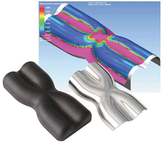
| Here’s another example of marrying forming simulation and 3D printing of hydroform tooling. Shown are Pam-Stamp models (thickness and major strain) of a formed aluminum (6062-O, 0.040 in. thick) heatshield, and the resulting 3D-printed form block created on a Stratasys Fortus 400mc printer. |
“Simulation programs essentially allow our customers to fail faster,” says Scott Pryer, hydroform application engineer for Triform Sheet Hydroforming. “It’s critical to determine quickly what doesn’t work, so you can move on to what does. Whether you’re quoting a new project and want to uncover hidden obstacles that might impact profitability, or are working with a delivery timeline that won’t tolerate re-do’s, forming simulations can save the day.”
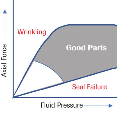
Powerful forming simulation suites also offer inside looks at valuable forming-process data. These insights can include material thickening and thinning diagrams, strain charting, force/pressure curves and measurements showing the distance from the material to the tool’s surface at any chosen location.
Step 2—Additive-Manufactured Tooling (3D Printing)
Facilities with access to forming-simulation software and 3D-printing technology can leverage the tool geometry, refined during the simulation process, for use in their 3D printer. The CAD data transfers wirelessly to the 3D printer, which converts the digital data into a three-dimensional object—layer-by-layer. Specific to additive-manufactured tooling for use in sheet-hydroforming operations, recent advances in print materials and processes have resulted in durable tooling able to withstand high forming pressures.
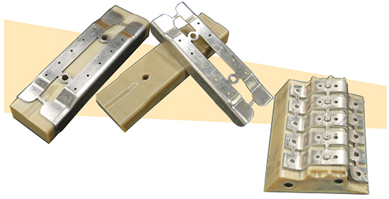 |
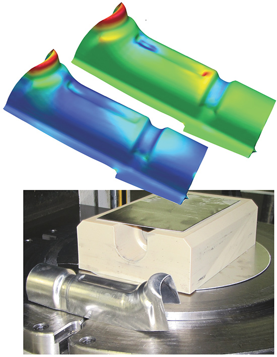
| Sheet hydroforming often allows for the formation of multiple parts in a single press cycle. Shown are sheet-hydroformed parts and their related 3D-printed tools, manufactured from Ultem 9085—a high-performance fused-deposition-modeling thermoplastic from Stratasys. The material can withstand hydroforming pressure to 20,000 PSI. |
While tool life hinges on several factors, including the 3D-printing medium, forming material and forming pressure, tools commonly last for hundreds of cycles before showing signs of wear. Dimensional accuracy reaches ±0.005 in.
The advantages associated with 3D-printed tooling revolve primarily around savings in cost and time. Additional benefits include lighter, more ergonomic tools that improve operator safety.
“Companies with 3D-printing capabilities can bypass their machining departments and send the tool geometry direct to the printer,” says Pryer. “Moving from traditional CNC machining to additive manufacturing requires little change in processes and procedures, yet offers significant reductions in hydroform-tool manufacturing time (60 to 80 percent) and costs (50 to 80 percent). And, with virtually no limit to the geometries that can be produced, 3D printing allows for on-the-fly implementation of design improvements.”
The 3D-printing process also supports repeatable tool creation without the need for third-party suppliers. Secondary tooling, such as drill and trim tools, as well as check fixtures also can be eliminated.
|
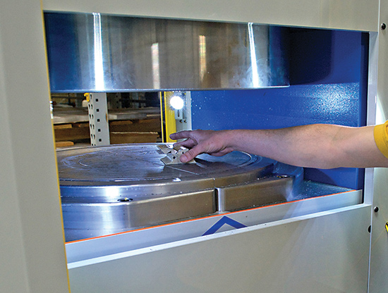
In March 2014, Steelville Manufacturing Co., a contract machine shop specializing in milling, turning, waterjet cutting and metalforming, took delivery of a new sheet hydroforming press (a Triform 24-5BD from Beckwood Press Co.) The bladder forming press features a 24-in.-dia. forming area with a maximum forming pressure of 5000 PSI. “Before the Triform, we often would form flanges and other part features in a press brake,” says Steelville engineer Joseph Dust. “We would also preform certain parts by forming them into stacked rubber against a male or female die, before finishing them in a secondary operation in a traditional stamping press with male/female tooling. With the sheet hydroforming press, we can bypass those processes and form our parts more quickly and efficiently.” This multistep forming process proved time consuming and expensive. In addition to increased engineering requirements, Steelville’s traditional methods also required considerable CNC labor and machine time. Its manufacturing team would have to design and manufacture mating dies for those parts which could not be press-brake formed, and those parts which were eligible for press-brake forming often would require multiple hits in order to fold multiple flanges on a single part. “Now, we can use the Triform to form a seven-bend part in less than one-fourth the time it would have taken in our press brake,” says Dust. While Steelville can create a single tool using poured epoxies and traditional machined materials, it has been an early adopter of 3D-printed tools. By using 3D printing to produce form blocks, Steelville bypasses its machining centers all-together. This collaboration between 3D printing and sheet hydroforming has dramatically shortened turnaround time for new-part production, while driving down overall cost per part. “We had been forming parts for years that we now know were tailor-made for the Triform,” concludes Dust. “Within the first week of having the press on our floor, we’d already moved more than 10 parts that now are being formed using the Triform process.” |
Step 3–Sheet Hydroforming
The last leg of our journey involves sheet hydroforming—forming sheetmetal using a flexible rubber diaphragm or bladder against a single tool or form block. Hydraulic fluid pumped into the bladder pressurizes it to supply a significant and evenly applied force on the entire part surface. Because the bladder acts as a universal die half that conforms to any shape within the forming chamber, only a single tool half is required—traditional matched die sets are eliminated.
Sheet-hydroforming tooling can be produced quickly and inexpensively from a variety of materials, including steel, aluminum, poured epoxies, wood and, of course 3D-printed materials. This dramatically improves new-part development time and lowers overall process costs, making sheet hydroforming ideal for rapid prototyping and short- to medium-volume production.
Summarizing his thoughts on the combination of simulation software, 3D-printed tooling and sheet hydroforming, Pryer adds:
“If you need to run production, you might still consider a traditionally machined steel or aluminum form block. But for proving out new designs or for low-volume part production, 3D-printed tooling is an extremely attractive compliment to the sheet-hydroforming process.” MFView Glossary of Metalforming Terms
See also: Beckwood Press Company, Triform Sheet Hydroforming
Technologies: Additive Manufacturing, Stamping Presses

 Video
Video