


Patented Slug-Control Grooves
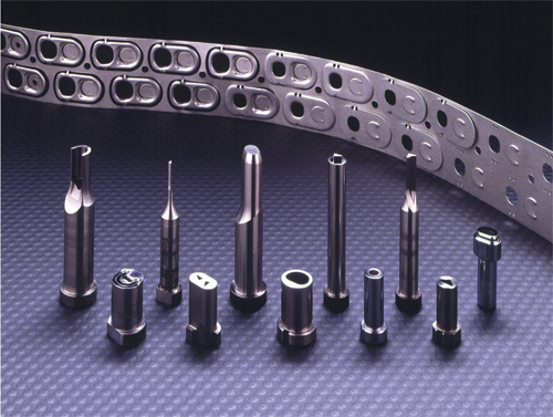
The practice of grinding precision grooves in the matrix land was designed specifically for high-speed stamping applications. The opposing grooves create small ears on the slug. The grooves spiral in opposite directions, holding the slugs to one side of the matrix to prevent them from pulling up when the punch withdraws.
The grooves vary in size based on material thickness and punch-to-matrix clearance, and can be applied to tapered and counter-bored relief matrixes as well as to shapes. They are ideal for use in applications where punch-to-matrix clearance does not exceed 10 percent per side.
Also during high-speed stamping, metalformers should keep punch entry to a minimum (0.015 to 0.030 in. is ideal) to prevent removal of the small tabs created by the grooves, but as much as 0.060 in. is acceptable. These tabs are essential for retaining the slugs in the matrix.
Tool-Steel Considerations
Tooling for high-speed applications requires a high degree of wear and temper resistance, typically indicated by a tool steel’s alloy content. While chrome offers some temper and wear resistance, molybdenum, tungsten and vanadium prove more effective when used in sufficient amounts.
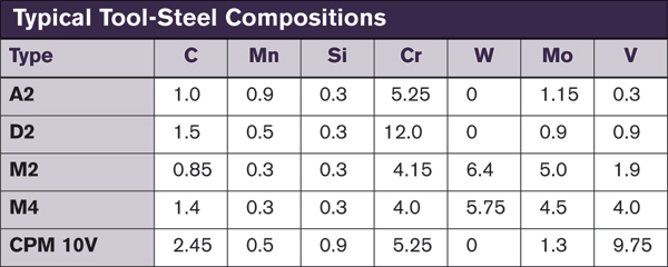 |
| Fig. 1 |
The chart (Fig. 1) lists some of the commonly used tool steels and their alloy content. Each alloy element listed in the table contributes to a specific characteristic in the finished steel. But these alloys also can create undesirable side effects, particularly when used in excess. Alloy elements also can react with each other, which may enhance or degrade the final result.
If toughness was the only factor in selecting a tool steel, S7 would be the obvious choice. Unfortunately, this toughness is achieved at the expense of other characteristics necessary in most stamping applications. Also, toughness tends to drop as alloy content increases. Higher alloy content also demands a higher price.
The manufacturing process also affects the toughness of a tool steel. The PM process can greatly enhance toughness of a given tool-steel grade over its conventionally made counterpart. For example, note the difference in toughness between M4 and CPM M4 (an alloy from Crucible Materials Corp.) in the chart below (Fig. 2).
Hardness also affects toughness. Any given grade of tool steel has greater toughness at lower hardness. Be aware that the lower hardness may have a negative effect on other characteristics necessary in achieving sufficient tool life.
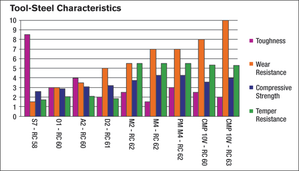 |
| Fig. 2 |
At first glance, high-speed stamping applications do not appear to require a great deal of force to perforate or blank parts, as parts generally are small and manufactured from thin, relatively soft material. Because the part material is thin and typically soft, it tends to stack up and jam in the matrix or die plate. If the punch lacks the necessary compressive strength, it fails.
Two factors affect compressive strength: alloy content and punch-material hardness.
Alloy elements such as molybdenum and tungsten contribute a great deal to compressive strength. Also, higher hardness of a given steel grade increases that steel’s compressive strength.
Alloys such as molybdenum, tungsten and cobalt that contribute to compressive strength also tend to improve temper resistance and red hardness. This is important in high-speed applications where heat buildup in the tool is a concern.
Temper Resistance
Temper resistance is the tool steel’s ability to maintain hardness after exposure to heat. Compromising hardness of a given tool steel reduces wear resistance and strength.
Several factors influence temper resistance. Alloy content is the primary contributor. The level of refractory-alloy elements—molybdenum, tungsten and cobalt—significantly affects a steel’s resistance to being tempered to a lower hardness. Other alloy elements, such as vanadium and chrome, also provide some temper resistance.
The temperature where a tool steel’s temper resistance is affected is directly affected by the tempering temperature used during initial heattreatment. A service temper within 50 F of the tempering temperature directly affects a tool steel’s temper. The bar graph (Fig. 3) illustrates the temper-resistant advantage of high-speed and high-alloy steels such as M2, CPM-M4 and CPM-10V over common cold-work tool steels like A2 and D2.
High load applications such as high-speed stamping of stainless, spring and HSLA steels call for tool steels with a combination of shock resistance and high compressive strength—M2 or CPM-M4 perform best in these applications.
Managing the Effects of Friction and Heat
- Galling—Relatively tight punch-to-matrix clearance often is used for slug control. The resulting tight fit of the part material around the punch point causes friction and generates heat. At high speeds the punch does not have enough time between strokes to cool. Therefore, heat builds up in the punch, causing galling and heat damage. Tool steels with high temper resistance minimize this type of failure.
- Heat Buildup—Punching small holes in high-speed applications requires special attention to tool-steel selection. Because small punches have less ability to dissipate heat, they are prone to overheating. This leads to loss of hardness, reduced wear resistance and dimensional instability. High-speed or high-alloy steels—M2 or CPM-10V —tempered above 1000 F have temper resistance superior to A2, D2 and other cold-working tool steels. This property makes them ideal candidates for high-speed conditions.
- Surface Treatments—Surface treatments often find use as a means to improve tool life. These treatments increase surface hardness and wear resistance, and reduce the coefficient of friction.
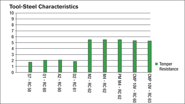 |
| Fig. 3 |
Important considerations when selecting a surface treatment include substrate material, coating-process temperature, coating thickness and coating hardness. A common treatment used for high-speed applications is nitriding, which case-hardens the surface of the tool steel. Fluidized-bed, salt-bath and gas are the most common and economical processes for nitride application. Ion nitride also is an effective process, but tends to be more expensive.
Titanium nitride offers better wear resistance than nitride, but experiences some difficulty with copper and stainless-steel stamping applications. Titanium carbonitriding provides even greater wear resistance in a broader range of applications.
“We also see today titanium-aluminum nitride becoming more common in high-speed applications,” adds Dayton Progress’ Angelo. “It creates a very hard coating, preventing galling and chipping, and also adds lubricity.”
A good rule of thumb concerning coatings, according to Angelo: Make sure the punch material has at least an 8 micro-in. finish or better. The coating follows the contour of the punch. The better the finish the better the adhesion of the coating and this dramatically reduces the coefficient of friction.
Application-Related Considerations
High-speed stamping requires metalformers to carefully consider strippers.
- Fixed strippers—Fixed strippers generally are not recommended for high-volume or high-precision applications. But, they do have a niche in high-speed applications. Because they have no moving parts, fixed strippers keep up with unique demands associated with high-speed stamping.
A fixed stripper is a steel plate with a clearance slot that allows the part material to pass under it. This plate mounts to the die retainer in a fixed position. Clearance holes cut through the stripper plate let the punches extend through without interference. At withdrawal, the part material hits the bottom of the stripper to prevent the material from lifting as the punch retracts. The part material strips from the end of the punch or punches.
Although fixed strippers are inexpensive and simple to maintain, they have several drawbacks. They do not hold the stock strip flat, and are unable to absorb impact and snapthrough shock. The result may be poor part flatness and premature punch failure.
The clearance under a fixed stripper commonly is set at 1.5 times the part material thickness. This clearance allows considerable material deformation under the punch points, often resulting in punch-point chipping. That deformation also can cause lateral movement of part and punches, resulting in punch-point breakage and poor part quality.
The sudden unloading of pressure on the punches and part material at snapthrough generates shock. This shock can lead to punch-head breakage.
Despite the disadvantages of fixed strippers, there is no limit to how fast the press can run before they become ineffective.
At withdrawal, the part material tends to buckle. This buckling binds the part on the ends of the punches, increasing stripping pressure and potentially chipping the punch face.
- Spring strippers—As the die closes, a spring stripper holds the stock strip, or part, flat in place during perforation and stripping, preventing the part material from lifting or hanging up on the punches. Use spring strippers in applications running at speeds to 1000 strokes/min.
When a spring stripper hits the part material, it bounces. At excessively high speeds it may not settle on the part before withdrawal, preventing it from holding the part flat and in proper location.
Stampers can take steps to reduce stripper weight to minimize bounce. Options include the use of lightweight materials such as aluminum, Inconel or titanium. Because Inconel and titanium have great strength, stampers can reduce stripper size, further reducing weight.
Removing material from the stripper is another to remove weight, done by drilling holes through the stripper. Chamfer the holes on the bottom side to prevent the stripper from marking the part. Strategically placed holes also can provide venting of air from between the stripper and the part to further improve the stripper’s ability to respond.
A spring stripper absorbs shock at snapthrough and eliminates shock at withdrawal that would otherwise damage the tooling and possibly the press.
In high-speed applications, keep stripper travel to a minimum. This also improves the stripper’s ability to respond.
Because the stripper lifts a from the part material after each stroke, visual monitoring of die performance is made easy: At high speed, use a strobe light to monitor the die.
Over-entry—or closing a die below its recommended shut height—can have catastrophic consequences.
Punch Stagger
Punches can be staggered in length to minimize impact and snapthrough shock. Typically, high-speed stampers opt to split punch lengths into two or three groups, reducing impact and shock by as much as 50 percent.
Common practice is to stagger the different groups of punches by an amount equaling stock thickness. Although this reduces initial shock, it does not reduce total shock. Each punch or group of punches is exposed to impact and snapthrough shock.
Making stagger equal to or slightly less than burnish length in the hole being perforated greatly reduces impact and snapthrough shock. This amount of stagger allows the next group of punches to contact the material prior to the first group snapping through. The snapthrough energy from the first group of punches is absorbed and used to drive the next group of punches through the part material.
Using burnish length instead of material thickness as the amount of stagger is extremely important in high-speed stamping applications. It reduces punch entry to minimize punch wear and slug pulling. Because the punches withdraw from the stock strip sooner, the stamper also gains more feed time.
Lastly, Angelo cites increased use of load sensors on high-speed tools. “We see sensors all over these tools now, primarily load sensors to uncover signs of tool wear,” he says. “In so many cases today, high-speed presses run untended and often enclosed in a sound barrier, so that operators cannot hear or even see what’s going on in the press. So, shops rely on load sensors to protect the integrity of the die for all functions and to decide when the punches have worn and need to be replaced.” MF
View Glossary of Metalforming Terms
See also: DAYTON Lamina Corporation, Crucible Materials Corporation
Technologies: Stamping Presses
Comments
Must be logged in to post a comment. Sign in or Create an Account
There are no comments posted.
Executive Interview with Bruderer Americas President AJ Rupp
February 2, 2024
 Video
Video
 Stamping Presses
Bruderer to Build New UK Factory and Showroom
Thursday, October 12, 2023