Peter Ulintz Peter Ulintz
Technical Director

Stretching and Drawing

June 1, 2009
0
Comments


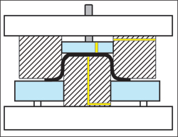
Troubleshooting forming problems in the press shop requires a good understanding of forming modes and process variables. Perhaps the most challenging forming modes to isolate are stretching and drawing. Because the process variables that influence each mode can differ significantly, an accurate assessment is essential before making changes to the tooling or stamping process. Changing a tooling parameter that promotes material stretching will not solve a drawing-related problem; good examples are punch and die radii. In stretching operations, the critical radius is the punch radius. The punch radius must be very smooth and large enough to promote material stretching across the face. The die radius is relatively small in stretching operations to restrict material flow over the die surface. In addition, the pressure pad is usually rough to inhibit material flow, thus forcing the material in contact with the punch to stretch.

On the other hand, the opposite parameters are required for drawing modes. Here, stretching material across the punch face is not desirable; therefore, the punch radius will be relatively small and the punch face left rough. The rough surface creates high friction between the punch and the sheetmetal, inhibiting material stretching, which in turn forces material to draw over the die surface toward the cavity. The die face and die radius are highly polished and the die-entry radius is made as large as possible—short of causing wrinkles—to ease material flow into the die cavity.

A brief comment regarding die craftsmanship and quality: In general, tool and die makers take great pride in their work. It is not uncommon to find every die component highly polished and meticulously prepared prior to final assembly. The polished components communicate a perception of quality to anyone that sees the die. Unfortunately, this quality perception can cause many problems. Regardless of the impression that a tool may leave, its primary purpose is function, not aesthetics. Smoothing and polishing the face of the draw punch, for example, significantly reduces friction in an area where friction is desired to help draw in the flange. One must be careful not to sacrifice function for aesthetics.

The location of die-process lubricant on the sheetmetal blank is critical in drawing and stretching operations. Stretching operations require lubrication between the sheetmetal and the punch face to provide a low-friction site for the material to slide and stretch. Meanwhile, the sheetmetal on the die surface should not be lubricated, creating high friction to inhibit material draw-in.

In deep-drawing processes, the sheetmetal surface under the punch should not be lubricated so there is higher friction between the punch face and workpiece. The die surface and die-entry radius should be lubricated to ease material flow. These very important lubrication conditions often are overlooked in the press shop. Often times, lubrication is applied to the entire sheet before it enters the die without any consideration for the forming modes. Small changes in lubrication quantity in critical zones on a stamping can mean the difference between drawing and stretching. Improper lubrication complicates problem solving and contributes to inconsistent part quality.

Pressure pads serve different purposes for stretching and drawing operations. In stretching operations, the pressure pad prevents sheetmetal movement under the pad. Because movement is restricted under the pad, the material in contact

Stretching and Drawing
Venting (shown in yellow) allow air and fluids to escape.
with the punch is forced to stretch. It also is beneficial to leave the surface of the pressure pad rough for stretching operations as this increases friction.

In deep-drawing operations, binder pressure (draw-pad pressure) is significantly reduced to permit material flow across the die face, yet high enough to prevent wrinkle formation in the flange area. The surface of the binder in contact with the sheetmetal usually is very smooth and polished to ease material flow. When deep drawing irregular-shaped parts, certain areas of the binder may be left rough to help balance material flow.

When wrinkles do occur, their locations on the part can help differentiate between stretching and drawing modes. Wrinkles on or around the punch nose indicate that restraining forces may be too low on the sheetmetal under the pressure pad. Pressure may need to increase to as much as 10 times the punch force, depending on material type and thickness. Increasing blank size, reducing or eliminating lubrication between the sheetmetal and the pressure pad, roughening the pad or adding lock-beads can also help.

Wrinkles in the flange area or near the die radius indicate the presence of in-plane compressive forces that are synonymous with deep drawing. Draw-pad pressure may need to increase to 40 percent of the punch force, depending on material type and thickness. Reducing the size of the die-entry radius (< 10t), adding draw beads and reducing punch-to-die clearance also may help.

Punch-to-die clearances in stretching operations usually are set to one times material thickness (1t). In drawing operations, compressive forces in the flange cause the material to thicken, which necessitates an additional 10 to 25 percent clearance (1.10t -1.25t), depending on material thickness and type.

The slide position where fracturing occurs can differ depending on the type of forming mode. Drawing failures generally occur within the first one-third of the draw depth. Forming loads (punch force) and friction are greatest early in the stroke and both diminish in magnitude as the blank area is reduced. Stretching failures usually occur near the end of the forming stroke due to excessive thinning and work hardening. Punch force and friction increase with stretch-forming depth.

Most tool-and-die professionals understand the need to vent draw dies (see illustration). Venting allows trapped air and lubricants to escape and prevents vacuum problems (part sticking) on the upstroke. Venting is very important for stretching operations, too. If venting is not provided, trapped air and fluids can cause bursting or fracturing in highly stretched areas. Unfortunately, after the breakage occurs, the fluid and air are released and the root-cause “evidence” disappears. Much time and effort can be wasted on tool modifications and material specification changes when the real culprit is trapped air and fluid.

Problem solving in the press shop can be greatly enhanced when you “stretch” your imagination before “drawing” conclusions. MF

Industry-Related Terms: Blank, Die, Draw, Drawing, Flange, Forming, Polishing, Stroke, Surface, Thickness, Work Hardening
View Glossary of Metalforming Terms

Technologies: Tooling

Comments

Must be logged in to post a comment.
There are no comments posted.

Subscribe to the Newsletter

Start receiving newsletters.