


Vibration Isolation
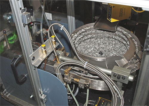
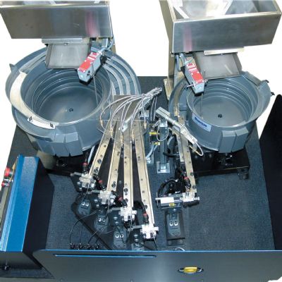
Patil then describes another significant challenge to designing the micropin feed setup: isolating the vibrating feed bowl from the rest of the circuit. So that only one pin feeds at a time through the 15-ft. line from the cart to the die, the setup features a shuttle that delivers one pin at a time from the bowl to injector-head assembly.
“To isolate the vibratory bowl from the shuttle,” Patil says, “there’s a 1-mm gap that each pin must pass over. Typically, this interface would be at 90 deg. to the feed axis. However, due to the small diameter of the fastener head, as the fastener moved across this gap the fastener head tended tip into the gap and get caught. To alleviate this issue, we cut the interface between the shuttle track and the bowl track at 45 deg. so that the leading edge of the fastener head transitions onto the shuttle track before it leaves the bowl track.”
Each micropin shoots into the injector head immediately after the retracting punch clears the fastener feed bore in the injector chamber of the head, Patil explains. The pin then enters the nosepiece, which captures and aligns the fastener, staging it for insertion.
“As the die begins to close and the stock strip is registered,” he explains, “the anvil pin protrudes up through the hole in the stock strip. As the punch descends and contacts the top of the fastener, the fastener becomes sandwiched between the punch face and the anvil pin, thus maintaining perpendicularity and alignment to the prepierced hole in the stock strip just prior to insertion. As the die reaches bottom dead center, the fastener passes through the prepierced hole and is clinched into the stock strip. Inserting and clinching in this sequence assures the micropin is installed within the required tolerances.”
Reliability and Repeatability
…always are concerns with any stamping operation, but perhaps more so with this setup. Mahnic explains.
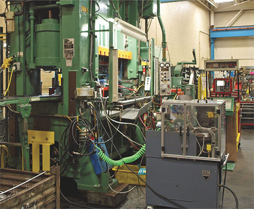
“When we first launched the tool, we dialed it down to about 25 strokes/ min. In a month or so we ramped up to 35 strokes/min., fine-tuning air-flow regulation and the layout of the feed tube. The feed tube is fixed to the press ram, and runs underneath the light curtain and loops back up to the stripper plate. We shortened the tube (to about 15 ft.) and positioned it to, as much as possible, get gravity on our side.”
Slug management also played a critical role in the project’s success. The bottom die half includes a specially designed slug-management system that uses a continuous vacuum to suck slugs out of the tool. “The ‘slug sucker,’ says Mahnic, “is tied to press actuation with its own channel on the Wintriss press control—the press won’t cycle unless that airline is hooked up and running.”
The final quality-control step in the process: periodic push-out tests to ensure the strength of each pin-to-stamping connection.
“We have to meet a 200-N strength requirement,” Mahnic says. “Initially, the specified diameter of the pre-pierced hole was too large to meet this requirement. We reengineered the hole and gained approval from the customer. Since then it’s been smooth sailing.
“If we were to run this process with the pin insertion as a secondary process, we could probably run the press at 60 strokes/min., Mahnic adds. “However, the customer understands well that the payoff for the extra cost of the in-die insertion equipment, and for running the press more slowly, comes quickly when accounting for improved quality control and efficiency of eliminating the secondary operation.” MF
View Glossary of Metalforming Terms
See also: Nidec Press & Automation, PennEngineering
Technologies: In-Die Operations, Stamping Presses, Tooling
Comments
Must be logged in to post a comment. Sign in or Create an Account
There are no comments posted.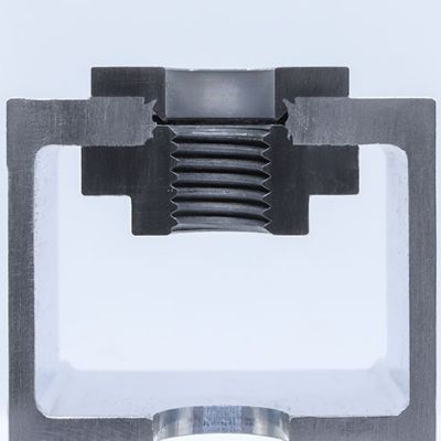 In-Die Operations
Spin-Pull Technology Enables Automated Clinch-Nut Installati...
Monday, January 31, 2022
Managing Horizontal Forces in Stamping Dies—Part 1
Peter Ulintz Thursday, April 30, 2020
 In-Die Operations
In Die Fastening, Part One—The Whys and Hows
Andrew Cooke Thursday, January 31, 2019
 In-Die Operations
Information-Laden Dies Require Your Attention
Peter Ulintz Friday, June 1, 2018