


 Peter Ulintz
Improving Hole Burnish and Cut-Edge Quality
February 1, 2014Comments
Shave operations generally are associated with burnished openings such as holes, but free-edge features also may be shaved. In fact, many die-cut features requiring close tolerances and burnished edges are good candidates for shaving.
Consider the 0.188-in. mild-steel plate shown in Fig. 1; red coloring indicates punched holes and shear edges requiring shaving operations. To determine proper punch sizes and required cutting clearances for punching and shaving, follow these process steps.
The shave punch will determine final hole size. This punch usually is made to the nominal part print dimension (0.375 in.) or slightly larger to allow for wear. However, when specifying shave punch diameters, remember that the resulting hole size will be slightly smaller than the actual punch size, usually by 0.0002 to 0.0004 in. due to elastic recovery after shaving. So, in this case we specify a 0.3753-in.-dia. shave punch.
The next step: determine the corresponding die-button (matrix) opening. Proper shave clearances must be very tight, usually 1 to 1.5 percent of stock thickness per side. Excessive clearance at the shave operation will result in shearing and fracturing rather than shaving. In the accompanying table, 1.25 percent per side clearance was used for shaving.
Specifying Punch and Button Size
Component
Pierce
Shave
Burnish
Punch-point diameter (in.)
0.3426
0.3753
0.3753
Punch-to-die clearance (in.)*
0.0374
0.0047
0.001
Die-matrix (button) opening (in.)
0.3800
0.3800
0.3763
*10-percent per side clearance assumed for punching (mild steel), 1.25 percent per side for shaving
The die button for punching the initial hole generally will be the same size as the shave station. However, a button as much as 2 percent of stock thickness per side larger may be required for softer steel and aluminum. Having a larger die button in the punching station minimizes the burr when shaving the hole.
Next we must calculate punch-to-die cutting clearance, as a function of stock thickness, and then subtract that clearance from the punch-point diameter.
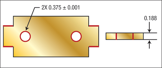
Fig. 1—Simplified Part (shaved edges in red)
When requiring high-quality surface finishes or very tight dimensional tolerances, the die builder may have to burnish the hole after shaving. Burnishing does not remove any material. Instead, it compresses the remaining surface irregularities to produce a high-quality precision hole.
The size of the burnishing punch is equal to the shave punch diameter plus 0.0002 to 0.0003 in. larger. The corresponding die button should be 0.001 in. larger than the burnishing punch.
Due to the close cutting clearances and high cutting forces associated with shaving operations, a guided stripper plate may be required to adequately support the punches and to maintain accurate punch-to-die alignment. This can greatly reduce punch chipping (a common problem) and premature wear or shearing.
Consider a chip-resistant tool steel for shave punches and wear-resistant tool steel or solid carbide for burnishing punches. Ensure a smooth ball-nose radius on the burnishing punch, blended perfectly with the point body. The ball radius and point body must be highly polished to minimize wear.
Other Considerations
The amount of material to be removed by shaving usually is 10 to 12 percent of stock thickness per side for most materials. This provides a good surface finish and leaves enough material in the scrap ring for slug retention. This is important—slug retention is one of the most common problems associated with shaving operations.
Shaving very thick materials with pronounced die-break or taper may require more than one operation. When employing two shave steps, the amount of material shaved in the second step should be one-half that of the first step. So, if a total of 0.027 in. of material must be shaved, remove 0.018 in. with the first shave punch and 0.009 in. with the second punch.
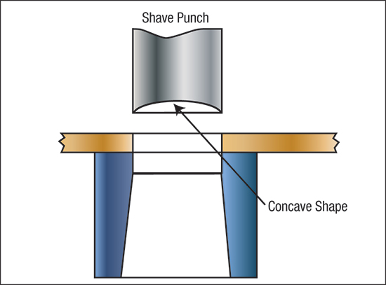
Fig. 2—Concave Relief
Shaving is much closer to a machining operation (cutting) than a stamping operation (punching). Therefore, consider adding a rake angle to the shave punch face similar to that found on a cutting tool. A conical shape on the punch face (Fig. 2) can accomplish this.
Establishing the proper back-rake angle for each shave application is somewhat of a black art that requires trial-and-error development. Some brass and bronze alloys do not require any back angle at all; mild steels, depending on hardness, may require a back angle of 10 to 30 deg.; and some aluminum alloys may need as much as a 45-deg. back angle.
When shaving a free edge (i.e. trim edges), the same rules apply. In addition, the back side of the shave punch must be heeled and properly supported to prevent deflection due to unbalanced cutting forces. Higher holddown forces also will be required to hold the workpiece in place during shaving.
Finally, carefully select the lubricant used for shaving. Depending on the type of material and its thickness, a heavy-duty EP lubricant used for fineblanking, broaching or in-die tapping may be necessary. MFView Glossary of Metalforming Terms
Technologies: Tooling
Comments
Must be logged in to post a comment. Sign in or Create an Account
There are no comments posted.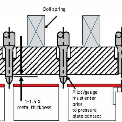
 Stamping Presses
Increasing Press Speed and (In)Efficiency
Peter Ulintz Thursday, March 30, 2023