Schaeffler supplements his materials-focused presentation with a talk on forming limits and the forming-limit diagram (FLD).
“A true understanding of simulation results and corrective actions is not possible unless the forming-limit curve is well understood,” he stresses. While a tensile test characterizes how a material in the shape of a dogbone behaves in tension, it doesn’t replicate the deformation experienced during the stamping of a particular part. The strains seen in every location on the stamping can be measured and compared with simulation.
“Do you need to specify a more formable grade to make the part,” Schaeffler asks, “or can you make some material or process changes that will lower the strains? To answer these questions and understand the capability of your chosen sheetmetal, you need to know ‘how high is too high’ when it comes to the strains. That’s where the FLD comes in.”
|
Special Roundtable Discussion: Methods for Ranking Progressive-Die Strips
The first step in processing a progressive die is to develop a strip layout. All too often only one strip layout is created. Even if several strips are developed, how does one determine which is best?
This discussion, led by PMA technical director Peter Ulintz, centers on how metalformers and die designers can rank strip layouts so that the best possible strip design is chosen. Strip layouts directly affect the final size of the die, initial die cost, die maintenance and repair cost, press selection, press maintenance and repair costs, initial stamping cost, in-process reliability, dimensional accuracy of the finished part, and the cost of poor quality.
“Financial business decisions often rely on multiple sources of data, such as financial statements, financial ratios, forecasting and investment analysis,” Ulintz notes. “But mission-critical technical decisions, such as the selection of a strip layout, which can affect the bottom line of a business for many years, often are based on a collection of opinions.”
Up for discussion: A numerical ranking system for evaluating and selecting the best strip layout. Evaluation scores can provide die engineers and process engineers with performance-based rankings for evaluating several strip layouts for the same part. Because the evaluation scoring has relative meaning for different layouts producing the same part, it can be used to find the best solution for that particular part.
|
Schaeffler will describe how to create an FLD, and the various techniques used to measure surface and thickness strains in the laboratory and in the field. He’ll then present the different approaches to counter failing parts.
“Even if a part is safe today,” he says, “the inherent variability in the stamping process and sheetmetal may result in future issues.”
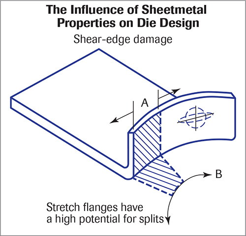
The Influence of Material Properties on Die Design
The discussion then turns to the impact that material has on a designer’s approach to die design. Learn from Peter Ulintz, PMA technical director, how material type, thickness, grade and temper specified for a given stamped part will greatly influence how the die should be designed and built.
“While die designs can be efficiently completed through the use of modern CAD software and the application of standardized components, this often comes at the expense of a thoughtful evaluation of the properties of the material to be formed,” Ulintz notes. “When the influences of material properties on the forming system are not known or understood, they cannot be properly controlled.”
It’s important to note that many rule-of-thumb guidelines used by die designers and toolmakers over the years may not be appropriate when developing tools for newer steel grades.
“For example, it has been a common practice for designers and toolmakers to apply 8 to 10 percent per-side cutting clearance for cutting and punching processes,” Ulintz says. “This may be an ideal clearance for mild steel, but it can be the worst possible clearance for many other steel grades in terms of burr height. Materials with low yield-to-tensile strength ratios, including many high-strength steels, require greater punch-to-die clearance to provide the mechanical leverage required to cleanly break the slug with a minimum burr. This requires increased attention to slug retention and scrap management in the die design.
“On the other hand,” he continues, “materials with high yield-to-tensile strength ratios (such as low-strength aluminum alloys) require much tighter clearances, making chipping, wear and abrasion more problematic. Also, small variances in cutting clearance—as little as 0.5 percent material thickness per side—can have a dramatic effect on burr height, sliver production and tool wear.”
 Springback compensation for high-strength steels and aluminum alloys also deserves careful attention, and Ulintz will address this during his presentation. And, some product and addendum geometry suitable for deep drawing of mild steel will not work for many aluminum alloys.
“Simple things like draw-bead profile design requirements can vary greatly between temper grades within a single alloy,” he says.
Introduction to Simulation Technology
This presentation, by Jeanne He-Dubois, Dynaform Product Manager, ETA—Engineering Technology Associates, Inc., covers the two basic simulation technologies: the inverse (one-step) method and incremental methods. Up for discussion:
- Simulation of drawing, springback, springback compensation, hydroforming, forging, trimline development, superplastic forming and hot forming.
- Advantages and limitations of simulation software.
- Differences between incremental and one-step solvers.
- A discussion of the explicit and implicit simulation methodologies, and element/time-step/mass scaling/dynamic effects.
“With increases in computing speed,” He-Dubois says, “the inevitable trend is the merging of simulation into the CAD environment. Designers now use simulation technology directly as they design a tool. Some CAD packages already have merged one-step analysis into their design flow, and it’s just a matter of time before incremental analysis will be inside of every CAD package.
“Full time simulation-engineer positions are shrinking quickly,” she adds. “I will discuss the impact this trend will have on the industry.”
Next-Generation Simulation Leads Engineering Beyond Just Validation
Adithya Ramamurthy, an application engineer at AutoForm Engineering USA, follows up with a discussion on using virtual simulation to identify potential forming issues that might occur during tryout and production. A subsequent trial-and-error approach can lead to identifying solutions to the forming issues encountered during evaluation of a simulation.
“The trial-and-error approach might work well for minor fixes or when a seasoned tooling engineer uses his vast experience for known issues,” Ramamurthy says. “It is a well-established fact that the trial-and-error approach, both in the toolroom and during simulation, can waste time and resources. Needless to say that the time consumption will only increase if the user is trying to identify a complicated or a non-existent solution.”
Optimization might be one way to overcome the limitations of a trial-and-error approach. “Most of the optimization tools run a loop of iterations until a good result is found,” Ramamurthy adds. “Optimization is selection of the best input value with regards to some criteria (thinning of 25 percent, for example). It loops through several iterations of the input to give an optimal value of thinning. If there are multiple results targeted, optimization becomes more time consuming and complex; or a solution can never be identified. With multiple ‘sensitive’ inputs, it becomes increasingly important to identify if there could ever be a solution associated to a simulation. Depending on the inputs, it’s possible that the simulation might never have a solution if certain input parameters are flawed. So a bad result is as important as a good one.”
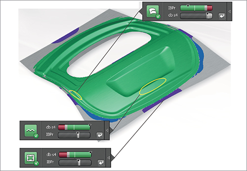
Ramamurthy will describe the use of systematic process improvement (SPI) and a robustness check of a virtual stamping process. Learn how new simulation software employs automated/manual issue detection to identify local forming windows, and then proposes a combination of design variants to address these issues.
“An entire range of input variables can be checked for a feasible ‘green’ simulation,” Ramamurthy says, “and an automatic combination of input variables can be configured for one or more issue types grouped simultaneously. A quintessential scenario would be when splits and wrinkles are grouped together as issues to be resolved. Here, the software will try to strike a balance between splitting and insufficient stretch on the panel.”
Die Quoting and Part Estimating
Eric Bragg, VP/sales engineer, TST Tooling Software LLC, then takes the stage to highlight software capabilities associated with developing initial die costs and piece-part costs.
“Quoting and estimating play an important role in keeping a die shop running successfully,” Bragg stresses. “Precise estimates are essential to maintaining a competitive and profitable edge.”
Bragg will describe the latest software features that help diemakers streamlines quoting, develop more accurate cost estimates and generate professional-looking customizable quotes. You’ll learn how to quicken your quoting process, produce more accurate estimates and better manage your quotes.
“The software also now allows shops to manage progression parameters and material utilization,” Bragg notes. “With each step the software will provide the tonnage needed for each operation. It also can quickly and easily simulate a realistic 3D strip with single or multiple parts; provide step-by-step unfolding information; and perform manual and automatic nesting.”
Lastly, Bragg will demonstrate how to quickly turn quotes into jobs, with automatically generated bills of materials, and with software fully integrated to work with existing CAD software.
Reverse Tonnage, Slide Tipping and More
This presentation highlights die simulation/animation technology and its application, including collision detection. Ray Proeber, president and owner of Accurate Die Design Software, Inc., will describe how progressive and transfer dies can be simulated in various press types such as conventional, servo and link-motion. Fineblanking, fourslide, multislide and Bihler machines also can be simulated. Attendees also will come away with a good understanding of slide-tipping prediction and reverse-tonnage loads.
“Reverse tonnage and slide tipping can wreak havoc on a punch press,” Proeber notes. “Unfortunately, they are overlooked often, sometimes until the press needs to be rebuilt because of them. Reverse tonnage in particular—also known as snapthrough or negative tonnage—can do significant damage to a press in short order. And, while slide tipping is not as destructive on the entire press overall as reverse tonnage, it can easily be addressed so that presses remain in good condition rather than suffering unnecessary, premature wear.”
When it comes to simulation, or looking at die kinematics, Proeber contends that a dozen years ago, die simulation merely was animating what would happen in a die, without any true interaction between the die components or even with the die components and the strip. Today, several simulation-software packages display very realistic die-operating conditions.
“Some of the software,” Proeber says, “can duplicate the conditions taking place in a 20-ft.-long transfer die, right down to predicting press speed for a given die, even before it hits the press. The tools within the software even account for velocity and acceleration.
“When people hear the word simulation, they often get nervous thinking that the software will be difficult to learn, to set up and to pay for,” Proeber adds. “This definitely is not always the case. The time savings downstream typically pays for itself many times over, based on the ability to detect collision problems and clearance issues before the die ever enters the press—much more efficient than catching and fixing problems later.”
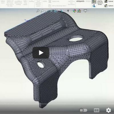
Case Study: Development and Optimization of a Deep-Drawn Transfer-Case Cover
Last but not least, all of the lessons learned come together with this case study presented by Peter Ulintz.
“Problems such as wrinkling, excessive local thinning and springback were investigated when forming a nonsymmetrical transfer-case cover,” he explains. “Wrinkling in the unsupported region between the punch and die was eliminated by placing various shapes of draw beads around the part periphery.”
This case study demonstrates how draw beads can help constrain material flow locally during the forming process. In addition, excessive thinning was observed where the vertical wall of the part was deep-drawn. In order to increase the minimum thickness of the drawn part, the blank was trimmed where the flange remains large after forming, to allow the material to flow more readily into the die cavity. At the same time, the blank was optimized by saving 35 percent from the original blank size. The minimum thickness was improved by 10 percent.
“Springback after forming also was investigated,” Ulintz adds. “Less springback was observed with proper draw-bead positioning and optimizing the blank profile. An incremental finite-element code was used to conduct finite-element computations to study the forming sequence and springback. The computational results were studied to determine the draw-bead shapes and locations. Then, prototype tooling was used to produce experimental parts to validate numerical results. The computation results showed good agreement with the experimental results.”
Interested in Learning More
…and attending the two-day conference? Visit www.metalformingmagazine.com/diedesign. MF
Industry-Related Terms: Alloys,
Blank,
Burr Height,
Burr,
CAD,
Case,
Die,
Transfer Die,
Transfer,
Draw,
Drawing,
Ductility,
Flange,
Forming,
Prototype,
Rockwell Hardness,
Run,
Scrap,
Slug,
Strips,
Surface,
Tensile Strength,
Thickness,
WrinklingView Glossary of Metalforming Terms
See also: ETA (Engineering Technology Associates, Inc.), Autoform Engineering USA, Accurate Die Design Software, Inc., CAMBRIO/Cimatron, 3D Systems
Technologies: Management, Software, Tooling


 Brad Kuvin
 Webinar
