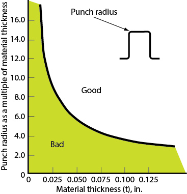
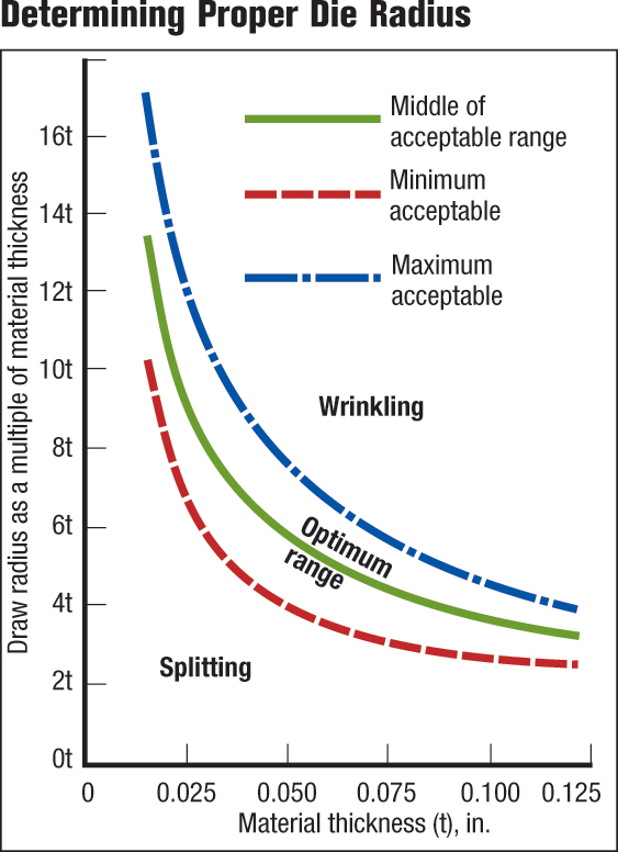
The LDR measured in the laboratory is not the absolute value that must be applied in the press shop. Like all forming operations, the product and die design are just two of many variables in the forming process. The LDR can be tweaked by proper design of punch and die radii based on sheetmetal thickness. The recommended punch and die radii as a function of sheet thickness are shown in Figs. 4 and 5, respectively.
 |
| Fig. 4 |
Redraws Needed for Larger, Narrower Cups
To achieve a good, robust process, die designers do not engineer ratios right up to the LDR, as doing so makes the process susceptible to other variables. For an LDR of 2.2, die design may be limited for production purposes to an approximate draw ratio of 1.9. Achieving a cup with a greater height-to-diameter ratio (Fig. 6) requires one or more redraw dies.
When redrawing operations are required, neither the shell diameter nor height approaches the final part-print size during early draw stages, so there’s no need to use the part-print radii. In fact,using a larger punch radius in the draw operation offers an advantage because the redraw blankholder fits inside of the drawn cup at this radius. This provides for a larger redraw radius on the blankholder, reducing bending and straightening loads for that operation.
 |
| Fig. 5 |
The redraw reduction percentage can never be as high as the first draw because the redraw has more bending and straightening forces, the cup wall in tension is smaller, and the material has been previously workhardened. Consequently, reductions for the first redraw usually measure 55 to 60 percent of the initial draw reduction. For example, given a first draw reduction of 48 percent, the first redraw reduction would be 48 percent initial blank reduction times 0.60, or 29 percent. The next redraw reduction percentage must be less than the first redraw due to more severe workhardening plus an even smaller cup wall in tension. As a rule, all subsequent redraw reductions are approximately 10 percent less than the previous redraw. Thus, given a first redraw reduction of 29 percent, the second redraw reduction would be 26 percent; the third redraw-reduction percentage would be 10 percent less than the second redraw, a 23 percent reduction; and the fourth redraw would be 10 percent less than the third, a 21 percent reduction.
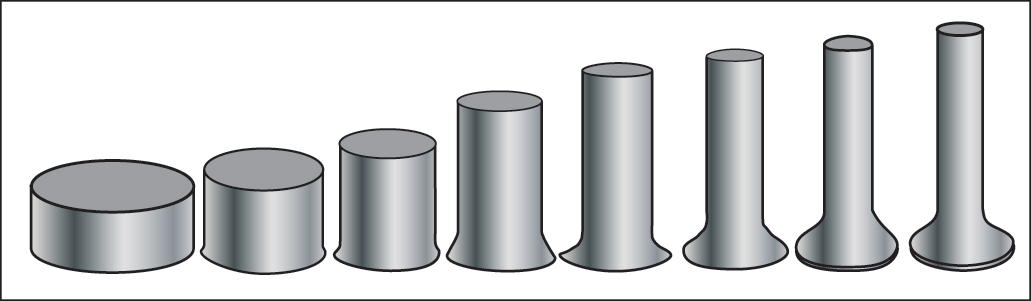 |
| Fig. 6—Achieving a cup with a greater height-to-diameter ratio requires one or more redraw dies. |
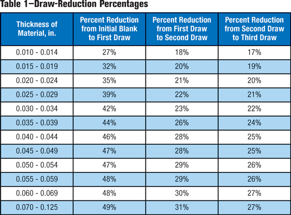
Suppose a final reduction is necessary in the fourth redraw, but requires only a 6 percent reduction. Building a fourth redraw tool for such a small reduction may not be cost-effective. Instead, a slight increase in the draw and other redraw percentages could eliminate the last redraw die. However, if the process is already critical, the initial draw and redraw percentages should be reduced to increase the fourth redraw reduction percentage and make it worthwhile. This pattern can be observed in Table 1. Different handbooks provide somewhat different reduction sequences.
To Flange or Not to Flange
Two types of redrawing methods are direct redrawing and reverse redrawing. Direct redrawing reduces cup diameter by redrawing the cup in the same direction as the first draw. In reverse redrawing, the cup is inverted during diameter reduction. Regardless of the redrawing method chosen, a decision must be made to draw the cup in the first draw operation with or without a flange.
Why leave a flange on the first cup draw?
- If the cup is to be produced in a progressive die, a flange may be needed for attachment to the carrier ribbons.
- It keeps the burr on the blank edge, a from the die radius. Drawing the burr down over the die radius can roughen or scratch the die radius, eventually leading to galling, and small slivers can be left in the die as bits and pieces of the burr break off. Die polishing and cleaning then become expensive maintenance costs.
- It reduces wall-thickening problems —the flange is the thicker part of the cup that stays under the blankholder.
Why produce a flangeless cup in the first draw operation?
- Once the critical punch load is passed as material flows toward the die radius, the amount of blank-edge movement becomes irrelevant. A general rule: Make the diameter of the initial blank edge as small as possible since forming severity is not increased. This is accomplished by removing the entire flange.
- Due to the design of redraw dies, a flange can be placed on a flangeless cup by controlling redraw-punch travel. The flange is created under the blankholder as shown in Fig. 7.
- If a flange has been left on the cup in the first draw operation, it is not practical to remove the flange or reduce its diameter in a redraw operation. The redraw-blankholder design will not prevent wrinkling if the flange is placed in compression. This also presents two other disadvantages: Leaving a flange in the draw operation creates an excessive amount of trim material, and lines or ridges will be left in the flange resulting from attempts to flatten or straighten the die radius from the first draw.
- Drawing a flangeless cup at each draw greatly simplifies cup removal by allowing the cup to be drawn straight through the die ring and allowing it to exit the bottom die by gravity, much like a pierce slug is forced through a die cavity and ejected out the bottom.
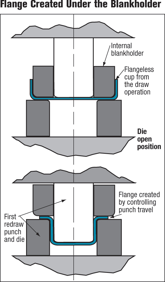 |
| Fig. 7 |
Need to Ease Material Flow
Redrawing also can create stepped cups by redrawing only a partial depth of the cup. Ironing is another option for extending the height of a cup without changing the diameter. Here the cup is redrawn through successive dies with increasing negative clearance between punch and die diameters. The wall of the cup thins as material extrudes back up the cup wall.
Frictional constraint also controls the ease of material flow from the blank into the cup wall. For a given blankholder force required to suppress formation of wrinkles and buckles, the lowest coefficient of friction lubricant is desired in the binder area. In contrast, high-friction conditions at the punch radius help restrict localization of deformation and possible tearing at the punch radius. This is especially true as the punch radius increases toward becoming a hemispherical punch rather than a flat-bottomed punch.
Interestingly, material type and strength have little effect on the LDR. True, the higher strength of the sheetmetal will increase the force required to pull it toward and over the die radius. Fortunately, the same higher strength increases the limiting force at the punch radius-wall junction capable of pulling the material into the wall. The two cancel each other to make the LDR material/ strength insensitive. The critical point in forming the cup now becomes avoiding a tear at very small punch radii.
Production of two-piece steel food and beverage cans offers an excellent example of strength cancellation. The production steel is full hard, having been given a cold reduction of 35 percent without subsequent annealing. Some beverage cans are formed by draw, redraw, three ironing stages and bottom dome forming—all at high forming speed without interstage annealing.
Tackling Cup-Wall
Thickness Differences
 |
| Fig. 8 |
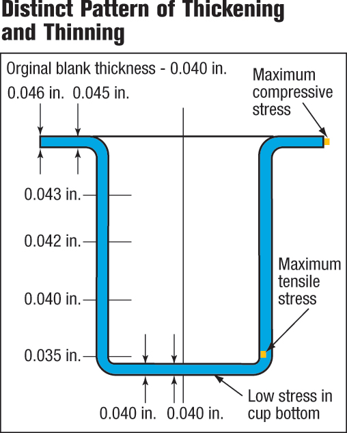
The change in cup-wall thickness at different locations within the cup presents a potential problem in cup forming. In Fig. 8, the cross-section depicts a distinct pattern of thickening and thinning found in flat-bottomed-cup drawing. Large compressive stresses are found in the flange where material has thickened considerably. In the cup wall, formed by a combination of compressive and tensile stresses, the amount of thickening diminishes as it approaches the die-impact (shock) line. Below the die-impact line, thinning is observed as the maximum tensile stress is found near the punch-nose radius. The small punch-nose radius, as shown, concentrates maximum tensile stress near the cup bottom where little or no deformation has occurred. No deformation takes place at the flat cup bottom where the material retains its original thickness. Deeper draws are possible when larger punch-nose radii are used because a larger radius shifts the maximum tensile stress site further down the cup wall, where the material has been strengthened by cold working. Differences in wall thickness can be corrected with an ironing operation.
Attack Box Drawing Like Cup Drawing
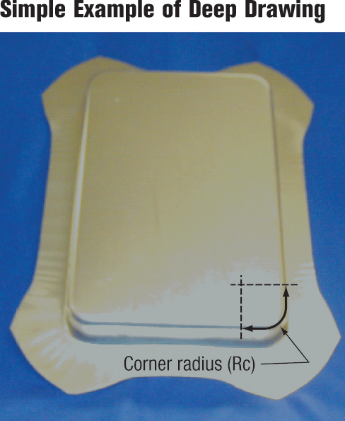
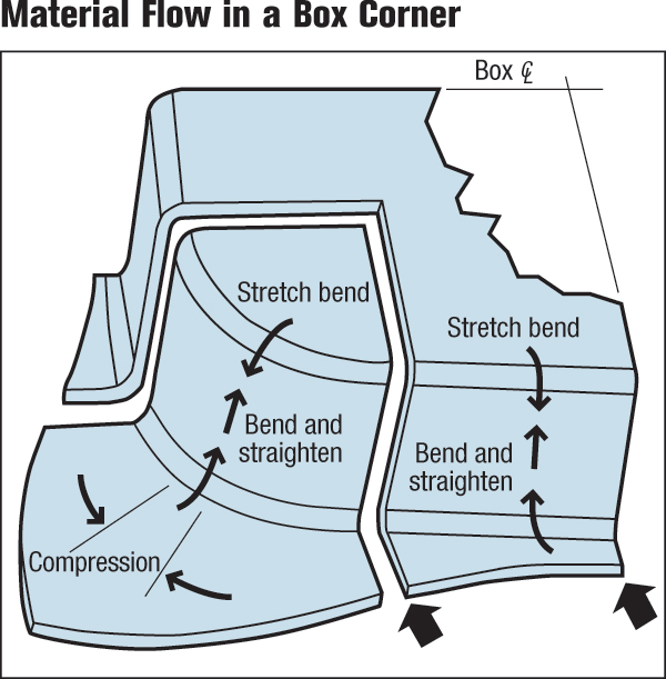
Now consider the four corners of any deep-drawn box (Fig. 1). If the sides of the box were removed, the remaining corner radii could be assembled into a cup. Subsequently, the corners of the box form in a manner similar to cup drawing. Radial tension in the corners pull material into the corners with circumferential compression placed on the material moving toward the die radius. Tensile forces act on the material after it is drawn over the die radius, with the material between the corners—the sidewall and flange area—also undergoing radial tension. Since drawing stresses in the corners are relieved by allowing some excess material to flow sides into the straight section, larger drawing ratios are achievable for box corners than for true cups of equal diameter.
 |
| Fig. 9 |
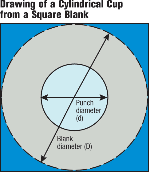
Note that the material flow in the corner of the box (Fig. 9) formed from a rectangular blank looks exactly like a cylindrical cup formed from a square blank (Fig. 4). The corner tab of the blank not only has a much larger than necessary draw ratio, but the triangular tab of the corner acts as a structural feature, preventing material from flowing into the sidewall area. Mitering and contouring the corners will improve the ability of the blank to flow into both the corner wall and the adjacent straight sidewalls. Inserting offsets, darts or other features into the straight sidewall near the corner will impede any compressive stress relief from the corner into the sidewall.
Several factors must be considered when deep drawing box shells, including:
- Size of the corner radius,
- Ratio between the corner radius and longest side,
- Material thickness,
- Size of the radius at the bottom of the shell,
- Width of flange,
- Shape of blank and blank-holder spotting,
- Type of die and press.
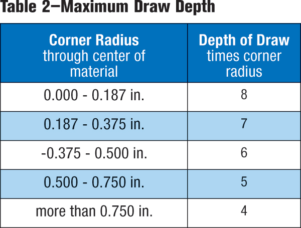
But the primary design factor is the plan-view corner radius and the ratio between the corner radius and the longest straight side of the box.
The size of the corner radius can be used to estimate the maximum draw depth for square boxes using tables similar to Table 2. These tables and formability curves reside in die-design and metalforming handbooks. In the absence of other data, these rules of thumb apply:
- Part depths less than five times Rc: one draw operation required;
- Part depths from five to 11 times Rc: two draw operations required;
- Part depths from 11 to 16 times Rc: three draw operations required;
- Part depths from 16 to 21 times Rc: four draw operations required.
Additional factors to be considered but often overlooked when deep drawing rectangular shells and irregular shapes include providing additional punch-to-die clearance in the draw corners to accommodate material thickening (Fig. 8). CNC machining the punch or die cavity with a simple offset for material thickness will not account for material thickening in these corners. Metalformers also should look to provide relief in the corners of the blankholder, also known as spotting in, to accommodate flange thickening in drawn corners. Forming severity can be further reduced by developing optimum blank shapes, increasing die-profile radius and improving lubrication.
Boxes with nonvertical (tapered) walls are more susceptible to wall wrinkles. Restraining forces must be increased and allowable box height decreased. A box design with tapered walls of 20 deg. may require a decrease in draw depth of 25 percent or more.
 |
| Fig. 10 |
Designing for Sidewalls
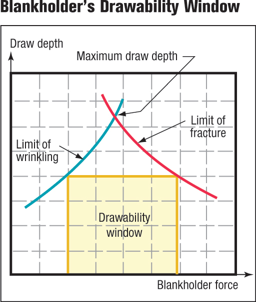
An important sidewall design consideration focuses on the ability to control movement of material from the blank to the die radius and up the sidewall. With several methods available to determine the amount of blankholder force required in drawing operations, the best practice is to use metalforming simulations (computerized die tryout). Forming simulations allow experimentation with blankholder forces until both a high limit (excessive stretching) and low limit (wrinkle formation) are established. The difference between the two limits, the blankholder’s drawability window, is shown in Fig. 11. The larger the window, the more robust the process will be to changes in blankholder pressure. As draw depth increases, the drawability window narrows considerably.
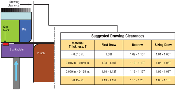
Excessive blankholder pressure can be remedied by using adjustable gap blocks, also referred
 |
| Fig. 11 |
to as stand-offs. Gap blocks allow higher blankholding forces without restricting material flow by providing a constant gap between the die face and the blankholder. Gap blocks are initially set at material thickness plus an additional 10 percent to accommodate material thickening due to circumferential compression in the blank.
Some industries use draw beads to assist in controlling blank movement in the sidewall area. This is particularly true of irregularly shaped panels commonly found in the automotive industry. Draw beads force material to bend and unbend before entering a die cavity. This creates a restraining force on the sheetmetal that causes the material to enter the die cavity at a reduced rate of speed. The height, shape and size of the draw bead and bead cavity determine the amount of restraining forces generated. For example, tight draw-bead and cavity radii decrease material flow, while large draw-bead and cavity radii allow material to flow more freely. Altering the height of the bead also increases or decreases the amount of restraining forces.
Plenty of Deep-Draw Info Available
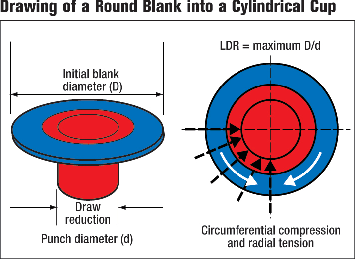
Unlike stretching and bending modes of deformation, deep drawing cylindrical cups from circular blanks can be a very robust process. Successful cup forming only requires the draw ratio to be less than the LDR. The LDR for a wide range of different materials and yield strengths hovers between 2.0 and 2.2. The LDR also limits the ratio of cup height to diameter. One or more redraw dies can create increased height or smaller-diameter cups. Various nomographs provide acceptable ranges of punch and die radii for different material thicknesses. Though cup design is restricted, correct design information is readily available.
Likewise, design parameters for simple deep-drawn boxes are well understood and available. The rectangular boxes act like four one-quarter cylindrical cups separated by straight sidewalls. Once draw beads or the blank-holder properly control material flow, the box corners become the critical design feature. MF
Industry-Related Terms: Bending,
Blank,
Burr,
CNC,
Coining,
Cold Working,
Compress,
Corner Radius,
Corner,
Die,
Draw,
Drawing,
Edge,
Flange,
Form,
Forming,
Lines,
Point,
Polishing,
Slug,
Thickness,
WrinklingView Glossary of Metalforming Terms Technologies: Pressroom Automation, Tooling