Tool Wear
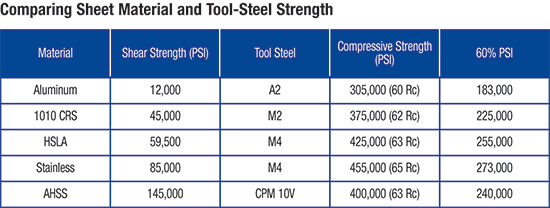 |
| Table 2—Courtesy of Dayton Progress |
…can be characterized as either abrasive or adhesive. Abrasive wear occurs when the tool material is being worn a, typically by friction. Stampers can reduce abrasive wear by increasing tool-steel hardness or carbide volume. However, this will reduce toughness and resistance to adhesive wear.
Adhesive wear results from microscopic welding at localized contact points between the tool- and work-material surfaces. During tool extraction, these microwelds shear. If shearing occurs on the tool surface, small fragments will be removed, leading to a gradual loss of material.
To reduce adhesive wear, increase the toughness of the tooling material and reduce the friction between the tooling material and workpiece. This usually requires the proper selection and use of lubricants, tool steel and tooling surface treatments.
Tool-Steel Selection
The most common tooling material for cold-working dies is D2. When used in AHSS applications, D2 can exhibit premature chipping and wear. To increase resistance to chipping and wear, consider a high-speed tool steel; in severe applications, a powder-metallurgy (PM) tool steel may produce the best results.
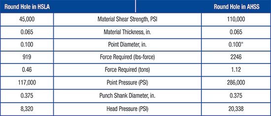 |
Table 3—Calculated head and punch-point pressures in HSLA compared to AHSS
|
PM tool steels have a unique microstructure characterized by small metal carbide particles uniformly dispersed in the steel matrix. PM tool steels, while more costly to purchase, often prove to be an economical choice due to their superior toughness and lower wear rates.
As sheetmetal strength and thickness increase, so will tool wear. This makes tooling hardness a prime concern. Hardness must be sufficient to resist plastic deformation, but not so high as to cause premature chipping or cracking. PM tool steels can achieve higher hardness after heattreat than conventional tools steels.
AHSS materials will subject punch heads and points to considerably higher loads than comparable-yield-strength HSLA steels. Table 2 compares the shear strengths for several sheetmetal grades, and compressive strengths for three tool-steel grades with various heattreatments. This table is for illustrative purpose only, since accurate shear data are difficult to obtain and a large range of shear strengths can be observed among the many different grades within each material type.
Punch Performance
For optimum punch performance, keep head pressures below 40,000 PSI. When head pressure exceeds 20,000 PSI, use a hardened backup plate heattreated to 45-50 Rc.
Punch-point performance peaks when maximum loads remain below 60 percent of the compressive strength of the punch-body material. Table 3 compares point and head pressures for an 0.100-in. punch diameter and equivalent sheet thickness (0.065 in.) in HSLA and AHSS materials.
The following example reveals the significance that AHSS materials will have on tooling design, tool-steel selection and heattreatment.
The calculated head pressure (Table 3) for the HSLA material is low enough to not require a backing pate in the die design. But, head pressure for the AHSS material exceeds 20,000 PSI, requiring use of a hardened backing plate in the die.
The compressive force acting on the punch point for HSLA is sufficiently low enough to allow the use of A2 tool steel heattreated to 60 Rc, without the loads exceeding 60 percent of the A2 compressive strength. Conversely, the force acting on the punch point for the AHSS material exceeds 273,000 PSI—60 percent of the compressive strength of M4 heattreated to 65 Rc. The M4 material and heattreat combination is marginal for the application; so punch life is significantly reduced as it may plastically deform over time.
This example only considers the compressive forces acting on the punch point. A punch machined from M4 and heattreated to 65 Rc likely would chip or break when cutting a material with 110,000-PSI shear strength. In this case, PM-M4 would be a better choice for improved resistance to chipping and wear, and for application of a surface treatment to further enhance wear resistance.
In general, optimum punch performance for blanking, punching and trimming is achieved through a combined balance of tool-steel toughness and wear resistance. MF
Industry-Related Terms: Abrasive,
Blanking,
Case,
Die,
Edge,
Forming,
Plastic Deformation,
Plate,
Point,
Shearing,
Surface,
Tensile Strength,
ThicknessView Glossary of Metalforming Terms Technologies: CNC Punching, Materials


 Peter Ulintz