Continuous Coil-Fed Laser Blanking
December 1, 2009Comments
Recent advances in laser-cutting technology have created a viable alternative to mechanical cutting of developed blanks from coil stock. While once laser cutting was deemed too slow for use in a mass-production line for developed blanks and only used for prototype and very-low-volume production of complex-shaped sheetmetal blanks, laser-cutting speeds now have increased to the point where the process can accommodate high-volume applications as well as low-volume opportunities occurring due to changing market requirements.
Ten years ago, laser-cutting equipment could typically cut 1-mm-thick steel at 30 m/min., using a CO2 laser rated at 10-percent efficiency and requiring complex external beam alignment. Today, laser-cutting machines can cut 1-mm steel at 60 m/min. with a 5-kW laser, and 4-mm steel at 13 to 15 m/min, while operating with a 30-percent power efficiency.
Beam and Servo-Motion Control
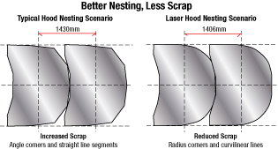 |
| Laser cutting prefers the same contour features as the forming process—large-radius curvilinear features, rather than straight segments and angular features—and allows for more flexibility in parts nesting, resulting in the need for less binder area and draw beads. |
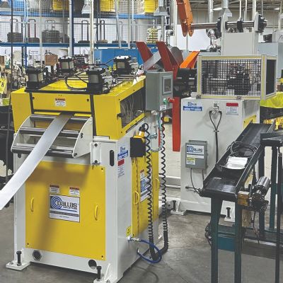
Advancements in the area of servo-motion control have contributed to expanding the range of laser-cutting applications to highly accurate and repeatable motion systems with high speed and high acceleration dynamics. Whether using ballscrew, rack and pinion or linear motors, the servo-motion control can work with the CAD/CAM application to produce an accurate cut contour of the highest quality, every time.
In order for a laser system to cut intricate angular and curvilinear features, it must be capable of high acceleration rates while maintaining a constant linear velocity through the complex nonlinear moves. These acceleration rates require higher loads for the actuators.
The control of the laser power has gone far beyond the typical analog signal tied to a power setting on the laser generator. The ideal laser control has morphed into a pulse-type control, where pulse length is modified to change laser output power.
New developments in CAD/CAM software allow the shape of a 2D part to be loaded in an assortment of different formats. This CAD information is used to create a nesting pattern that optimizes material usage, and a corresponding cutting-path routine to operate the laser-cutting machine. At all stages of the process, manual intervention can occur to easily introduce different requirements than might typically be expected. The urge to design as many straight-line segments into the blank contour, creating corner angles in order to simplify the blanking die, no longer is required. These blank shapes, intended to simplify the blanking-die design, limit the ability to optimize raw material usage. Conversely, in accordance with the drawing or forming processes, laser cutting yields blank contours with adequate curvilinear features that can increase blank formability.
Automotive Trends: Higher-Strength Steels, Lower Volumes
The increased use of advanced-high-strength steels requires higher-tonnage blanking presses. Tools wear more quickly and the quality of the cut edge becomes an issue when the number of micro fractures that occur along the cut edges of the blank increases. These micro fractures can develop into splits during forming. Laser blanking eliminates these issues, as material tensile and yield strength have little or no impact on laser-cutting speed, and there are no micro fractures produced during laser cutting.
Also, as automotive OEMs have decreased model volumes, the investment required to manufacture a part can no longer be spread out over a large number of parts. This is where laser blanking shines, by eliminating the need for a dedicated tool. A typical blanking die, depending on its size and contour complexity, can cost as much as $250,000. If the annual production of a part is 300,000 units, the die adds nearly $1.00 to the piece price of every part, not accounting for the value of the initial time investment made prior to the actual manufacturing of the part. Manufacturing costs will include variable costs such as labor, utilities, consumables, repair, maintenance, and overhead and expenses related to production.
Operational Saving with Laser Blanking
Laser-blanking lines provide an operational cost advantage over traditional blanking lines. They avoid the need to build a press pit, and certain configurations eliminate the need for a coil looping pit. Other avoided costs include those for high crane capacity and die-storage and die-change requirements.
Of course, laser cutting also provides flexibility. Modification to the cutting program for a developed blank is one of the most identifiable flexible features. With laser cutting, the program can be modified with a simple 2D CAD software program. Costly changes that would take days to implement with a die can be made at virtually no cost, and in only a few minutes of reprogramming time. Whereas the typical nesting routine for mechanically blanked parts has many rules based on the type of punching or shearing used to cut inside the blanking die, laser cutting simplifies the process and expands the nesting opportunities to maximize coil utilization and minimize engineering scrap. This is particularly evident when using common-line laser cutting.
There are other potential savings advantages that have not even begun to be understood. For example, consider the ability to nest two different parts of like thickness in the same strip. With laser cutting, the processor can change a part nest so that the same coil width is used for different parts of the same thickness, or it can nest different parts made from the same material thickness in a variety of different s to minimize the scrap produced during blanking. There no longer are limitations to a set progression based on the length of the press bed.
Scrap Reduction
Typical overall engineering scrap for automobile body-in-whites (BIW) averages a staggering 40 percent, unavoidable because forming requires binder material to hold the blank with the proper tribology to control its successful flow by the punch in the die. This binder material, along with other functional holes in the final component, is trimmed out to have the exact dimensional shape per the end product’s design.
To enhance formability, the binder area sometimes receives favorable contour features. Trying to nest these contours in a coil progression to optimize material utilization results in engineering scrap distributed between the blanking process and the post-forming process. However, since laser-cutting prefers the same contour features as the forming process—large-radius curvilinear features, rather than straight segments and angular features—it allows for more flexibility in parts nesting (see the figure), and results in the need for less binder area and draw beads. The net result, on average, is at least a 3 percent reduction in scrap per BIW.
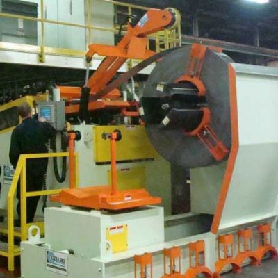
From Automated Blank Feed to Coil Feed
Traditionally, laser-blanking lines receive large rectangular sheets of varying thicknesses and cut them into smaller, nested contours. Automated shuttle tables and part-removal systems reduce labor content and improve productivity.
 Video
Video