Peter Ulintz
A Single Punch and Shave Tool
August 18, 2010Comments
Question: A couple of months ago you wrote a column about shaving (A Close Shave, July 2010). The information in your column related primarily to two-step shaving operations; punching a hole first and then shaving it in a second progressive die station or die operation.
One of our customers wants to improve the punch-hole condition in one of the stampings that we currently supply but we do not have room in the die to add an additional shaving station. Are you aware of a reliable method(s) for punching and shaving in a single press stroke?
Answer: Over the years I have seen some single-stroke punch and shave tools, often referred to as step punches, that have worked well, and many that have not. The primary problems with step punches have been slivers in the die, slug-ring ejection and increased tool wear. Satisfactory results usually come only with great effort and much trial and error. Step punches in high-volume stamping applications also will require an increase in the amount and type of die maintenance required.
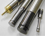 |
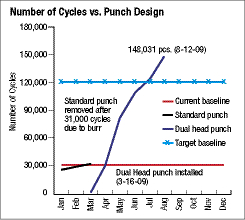
| Fig. 1—A dual-head punch. |
For the most part, each step punch application is its own R&D project and, therefore, developing an empirical formula or standard designs for general use has proved extremely difficult, if not impossible.
Many of the problems associated with step punches are due to the elastic behavior of the sheetmetal being punched. Remember, when punching holes using conventional punch-to-die clearance (approximately 5 to 8 percent per side) the punching stress forces the material around hole-edge periphery outward into compression. When the slug breaks free, the compressive stresses relax and the punched hole “springs back” (inward) toward the punch point. The opposite occurs when engineered cutting clearances (approx. 9 to 20 percent per side) are applied. In this case the punching stress pulls the material around the punch hole-edge periphery inward in tension and then the hole springs outward (a) from the punch point when the slug breaks free.
When a punched hole changes size during the punching stroke, it is difficult to accurately recut the hole and maintain the necessary shave clearances. Worse yet, because the hole often changes shape during the second cutting (or shaving) step, problems such as chipping, wear, galling and/or adhesion arise in as little as a few hundred hits.