


 Peter Ulintz
Technology Forum for Die Shops
January 1, 2017Comments
PMA’s Metal Stamping Technology and Tool & Die Conference, held December 6-7, 2016, in Chicago, provided a forum for learning and discussing new technologies and best practices for metal-stamping processes and tool and die design and construction. A prevailing theme for the tool and die community: Challenges associated with new or unfamiliar materials, and the ability to design robust stamping tools to process them. Stamping companies and die shops whose primary experience is with mild steels and high-strength low-alloy steels often struggle to produce parts from high-strength aluminum grades, stainless steels and advanced high-strength steels (AHSS).
As lightweighting applications continue to expand, in automotive and other industries, Tier suppliers increasingly encounter the need to engineer tools and produce stampings from these materials. Several presentations in Chicago addressed common tooling issues and key considerations for designing and building dies, including topics on AHSS tool-steel technology, advancements in nanoparticle ceramic coatings, aluminum technology and stainless-steel applications.
In several conference sessions, speakers underlined the importance of proper cutting clearance between punch and die components. They emphasized that the appropriate cutting clearance depends highly on material type, alloy, temper and sheet thickness.
Appropriate maintenance routines, sharp tooling and precise die alignment become extremely important when punching and cutting aluminum alloys, especially dead soft alloys (O-temper). Poor tooling alignment and dull punch edges produce burrs (similar to those caused by excessive clearance) that can break off in the die—a primary cause for fine slivers in the die.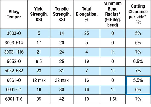
Minimum mechanical properties for 0.060-in.-thick sheet (Ref. ASTM B209) *ASM Specialty Handbook: Aluminum and Aluminum Alloys
A presentation on design guidelines for aluminum stampings emphasized the importance of being very precise in terms of cutting clearance. For instance, the accompanying chart prescribes recommended cutting clearances for several aluminum alloys and tempers. At first glance, one might think there is not much difference between 5.5-percent material-thickness cutting clearance and 6-percent material thickness. How important can 0.5 percent be?
The presenter offered an analogy, converting the percentages to money. If someone bought a stock, he said, for $5.50/share and its share price increased to $6.00, the increase in value is almost 10 percent/share. The same holds true for cutting clearances—the increase from 5.5 to 6 percent/side is an increase of nearly 10 percent per side. That’s significant.
Proper clearances for deep-drawing applications, especially in drawn corners, also was emphasized at the conference. With modern CNC programming, it is easy to generate a tool path and offset the cutter by maximum material thickness to provide clearance between the draw punch and cavity. This works well, until a drawn corner is encountered. Here, the corners of a draw are forced into compression, which causes the material to thicken in these areas. Additional clearance is required where the thickening has occurred. For draw-quality mild steels there may be as much as a 10-percent increase in thickness. This often is overlooked when tool paths are being generated and can become a primary cause of galling in drawn corners.The problem is further exacerbated when deep drawing other materials. One presenter suggested that some high-strength aluminum alloys may need a clearance of 15 to 20 percent, while some austenitic stainless steels may require a clearance exceeding 35 percent.
A common misconception about deep drawing of stainless steels is that they are less formable than mild steels, because they workharden so much. In reality, many grades have substantially higher ductility than plain-carbon steels and frequently are deep drawn into very complex shapes without the need for intermediate annealing. Even the less-formable ferritic grades provide outstanding ductility.
Increased blankholder forces also will be required for deep drawing aluminum stampings since aluminum grades have a Young’s modulus one-third that of steel. The reduction in Young’s modulus increases the likelihood for wrinkling, oil canning and surface distortions, while increasing the magnitude of springback by a factor of three (compared to steel sheet of equivalent yield strength).
Blankholder-pressure requirements for stainless steel will be much higher than for low-carbon drawing steel. The ferritic grades (430 for example) require about 50 percent more pressure, while the austenitic grades (304, 316 for example) may require as much as three times the applied force of that needed for low-carbon steel. This is an important factor to consider when evaluating press energy and tonnage capacities during press selection.
If you did not attend the conference this year, you missed a lot. Plan to attend the next edition of the PMA Metal Stamping Technology and Tool & Die Conference, in January 2018 in Nashville. Interested in presenting? Contact me at pulintz@pma.org. MF
View Glossary of Metalforming Terms
Comments
Must be logged in to post a comment. Sign in or Create an Account
There are no comments posted. Materials
Steel’s Boundless Value Proposition
Brad Kuvin Friday, March 29, 2024