Lou Kren Lou Kren
Senior Editor

Tool Design and Build Made SIMple

April 1, 2016
0
Comments


With more than 30 years in the trade, Brian Mason recalls stamping-tool design, build and tryout years ago.

“Back in those days, when you wanted to try something,” he says, “we had to machine pockets, order steel, fit the steel in and work out all of those shapes through trial and error. We had a ton of machining time and wasted material. And back then, we didn’t even have high-strength steels with all of the springback and other challenges. We just had to worry about concepts and how to make the part, not how to deal with the material springback. Even so, turning around a die was as long as a 75-week process.”

Tool Delivery Cut by Two-Thirds

Today, Mason, as simulation and tool processing manager with Walker Tool & Die, Inc., Grand Rapids, MI, and his staff deliver ready-to-run automotive dies to Tier Ones and OEMs in less than a third of the time. He credits much of the speed gain to simulation software.

Specifically, Walker, in its quest to supply production-ready tandem and mechanical transfers dies as well as progressive tooling for automotive and appliance parts to 9 mm thick, relies on simulation software from AutoForm, Troy, MI.

“We’ve used AutoForm since 2011, and are especially happy with the features and computation speeds,” says Mason, pointing out that this simulation program is particularly speedy compared to programs the company had used before.

“We can perform six to 10 iterations in a day on some parts where, before, we would get one,” he explains.

Seven Walker employees in Mason’s department conduct simulation—four AutoForm seats are used for simulations, with three more providing modeling support such as unfolding and nesting of blanks. These seats also sometimes perform simulation. Nine solvers support the simulation work.

In practice, Mason’s department employs simulation from the start of a project, bringing a part into AutoForm to develop a forming process. From there, Walker’s design department develops a tool around the surfaces developed. The teams then work back and forth throughout the design process.

“Sometimes when the projects get to tool design,” Mason says, “we’ll find that an idea we had is not always feasible, so we will modify the concept to create a workable tooling and manufacturing environment For some of our more complex parts we use AutoForm’s Die Designer software to quickly experiment with different tips, draw depths, binder shapes and addendums to create feasible processes.

With decades now under its belt, simulation software has evolved to gain a whole new level of trust with its users, and that is especially true for Mason and his trust in AutoForm.

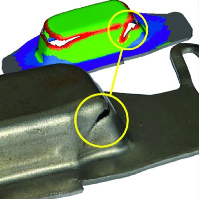
“If there’s an issue in simulation, there definitely is an issue on the shop floor,” he says. “Our customers, internally and externally, depend on us to work the bugs out before we ship the tools to the floor. If we don’t have a green simulation (that is, a very good process worked out in simulation), we do not move ahead with the die-build process until it is cured.”

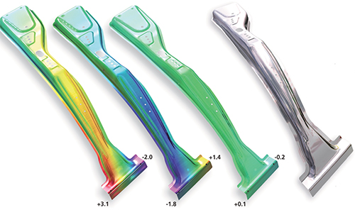
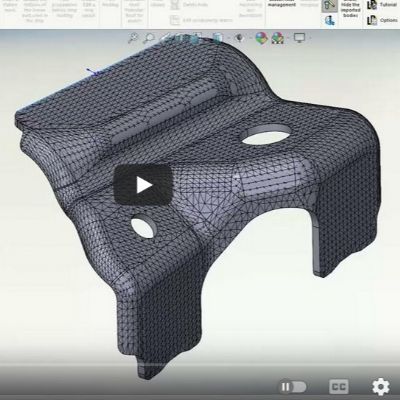
With the software’s speed, Mason’s team can afford to be thorough and creative without sacrificing lead time. A recent case in point: A challenging high-strength, low-alloy-steel cross-member for an OEM pickup truck of high-strength low-alloy steel, which underwent dozens of iterations to arrive at an acceptable green process.

Simulation Tackles Increasing Springback Challenges

Working with higher-strength materials on projects such as this has become the norm at Walker, where more and more of these materials find their way into automotive and even appliance parts. For that reason, Mason and Walker make extensive use of AutoForm’s springback-compensation module, AutoForm-CompensatorPlus. The module allows users to automatically modify tooling surfaces based on precise springback calculation. Engineers can define compensation regions, which the software automatically adjusts using the springback results, with that compensated geometry then used for rapid and accurate tooling validation. Either the entire tooling surface or selected regions of a die face may be defined and modified. Defining these different regions allows for systematic compensation control, according to AutoForm officials, because compensated tooling geometry is automatically used as input for the next simulation.

 
Simulation software has allowed Walker Tool and Die to successfully attack springback, which has become more prevalent with the increased use of higher-strength materials in automotive applications. The first three images at left show how springback is compensated for in an automotive B-pillar through successive forming-simulation iterations, with the image at right showing the final part.

For example, Walker recently took on an automotive OEM project using DP 980, where springback on existing tooling was “way out of control,” says Mason.

“We dropped the project into AutoForm and modified the process to develop the tip and addendums to better attack springback. We saw a big benefit in using simulation for this springback challenge.

“Very seldom do we see mild-steel parts anymore,” Mason continues. “AutoForm’s solvers recognize the hardening that occurs as high-strength materials are being formed, known as kinematic hardening, as well as other problems such as sidewall curl and splits in secondary operations. Even with all of the new challenges encountered when working with high-strength materials, iterations are performed several times more quickly than before.

“We do all of our tryouts here, all of our quality loops where we have to recut the shape of the tool to compensate for material movement during forming,” he continues. “I’d say we have cut out 50 percent of the quality loops on a majority of our parts by attacking springback in simulation.”

To add even more accuracy and speed to the process, Walker tests its part material and uses the properties gleaned to generate specific stress-hardening curves, which it imports directly into AutoForm.

“That’s a big benefit as opposed to just using a generic curve, and gives us the best results,” says Mason.

Trim-Line Optimization Adds Accuracy, Cuts Modeling Time

Trim-line optimization is another area where simulation software shines for Walker.

AutoForm-TrimPlus in combination with AutoForm-SolverPlus is used to help determine blank outlines and to ease the tryout of trimming dies by finding the optimum trim line. The trim line is optimized to ensure that the desired shape and dimensions of the part boundary are obtained at the end of those operations that follow the trimming operation. AutoForm-TrimPlus automatically adjusts the trim line to remove or add sheetmetal until the desired part boundary is achieved.

“The software evolves our trim line behind the scenes so that we don’t have to perform all of that manually,” says Mason. “That can save us upfront in modeling time.”

Optimum blank outline is important when near-net-shape manufacturing (crash forming). The blank outline is optimized to ensure that the desired shape and dimensions of the part boundary are obtained at the end of the crash-forming process. The advantage of incremental over an inverse one-step simulation, which also can be used to find the blank outline, is the consideration of not only one, but several forming steps, and results in much greater accuracy, according to AutoForm officials.

Walker Tool and Die also uses AutoForm during the quoting stage for difficult parts.

“We use it to prove feasibility and to propose product changes for parts that are not formable,” Mason says. “The software is used to obtain an accurate blank as well as for estimating press tonnage.” MF

Industry-Related Terms: Case, Die, Draw, Forming, Lead Time, Nesting, Point, Surface, Blank
View Glossary of Metalforming Terms


See also: Autoform Engineering USA

Technologies: Software, Tooling

Comments

Must be logged in to post a comment.
There are no comments posted.

Subscribe to the Newsletter

Start receiving newsletters.