 |
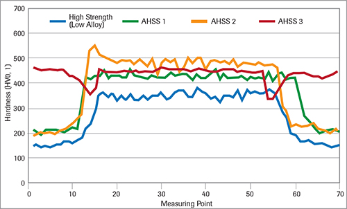
| Fig. 3—Hardness distribution through spot welds on various grades of AHSS. |
Again, all three DP steels had similar weld-hardness distributions (Fig. 3). The study also concluded that weld fracture mode alone is not a good indicator of weld integrity and performance. The load to fracture should be considered more important in judging weld integrity.
A second study compared 1.6-mm-thick DP 420/700 and TRIP 420/700. Weld-current range for 18 cycles of weld time was 1.4 kA for the DP steel and 1.5 kA for the TRIP steel. Average weld hardness was 400 HV for both steels. The study concluded that acceptable welds with no imperfections can be produced in both grades, and both grades are readily weldable with easily adoptable welding parameters. Weld tensile-strength differences between the two steels were small and not considered statistically significant. Weld schedules with pulsed current profiles for AHSS can have weld-current ranges similar to mild steel.
Heat input must be changed depending on the steel thickness and grade. Compared to lower-strength steel at a particular gauge, an AHSS grade at the same gauge may need less current. Similarly, the thin-gauge material needs less current than thick gauge. Controlling heat input during RSW according to the gauge and grade is called heat balance.
Understanding Heat Balance and Electrode Life
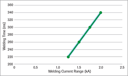
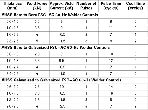 |
| Weld schedules for RSW of bare and galvanized AHSS. |
For a particular steel grade, changes in thickness may require adoption of special weld schedules to control heat balance. Due to the higher resistivity of AHSS, weld-nugget growth occurs preferentially in AHSS. Electrode life on the AHSS side may be reduced due to higher temperature resulting from high bulk resistance and high material stiffness. In general, electrode life when welding AHSS may be similar to mild steel because of the lower operating-current requirement due to higher bulk resistivity in AHSS. This increase in electrode life may be offset in production due to poor part fitup created by higher AHSS springback. As electrodes wear, tip diameter increases, which then requires an increase in welding current and electrode force. Also, frequent tip dressing will maintain the electrode-tip shape and help achieve consistently acceptable welds.
AHSS grades can be welded with power sources operated using AC or DC. Middle-frequency direct current (MFDC) has an advantage over conventional AC due to unidirectional and continuous current. These characteristics help to control and direct heat at the interface. Current mode will not cause any significant difference in weld quality. Some research also shows that MFDC current can improve electrode life.
AC and DC can easily produce acceptable welds where weldment-component thickness ratios are less than 2:1. However, some advantage may be gained using DC where thickness ratios exceed 2:1, but welding practices must be developed to optimize the advantages. It also has been observed that nugget sizes are statistically somewhat larger when using DC welding with the same secondary weld parameters as with AC. Differences in current-wave characteristics will change dynamic resistance during welding, which impacts weld-nugget growth.
Some studies have shown that welding with MFDC provides improvements in heat balance and weld-process robustness when there is a thickness differential in AHSS. DC power sources reportedly provide better power factors and lower power consumption (by about 10 percent) than AC power sources.
Ship-Shape Weld Tips
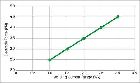
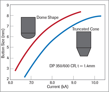 |
| Fig. 4—Effect of welding-electrode geometry on current range when using AC power mode and a single pulse. |
AHSS can be welded with all weld-tip shapes (truncated cone and dome) and materials (Fig. 4). Dome-shaped electrodes ensure sufficient buttons even at lower currents due to higher current densities at the center of the dome shape. The curve of dome-shaped electrodes will help to decrease the effect of electrode misalignment. However, dome electrodes might have less electrode life on coated steels without frequent tip dressing. Due to round edges, the dome electrode will have fewer tendencies to develop surface cracks when compared to a truncated electrode.
Resistance welding depends on the resistance between two sheets. While good and consistent part fitup is important to all resistance welding, fitup is even more critical when welding AHSS due to increased yield strength and springback. In the case of poor or inconsistent part fitup, large truncated-cone electrodes are recommended for AHSS, as well as conventional steels. The larger tip size will have a larger contact area, which results in lower current density, thus it will have larger current range. Also, fabricators can use progressive electrode force and upslope to overcome poor fitup.
What about Coated AHSS?
AHSS grades are commercially available with hot-dip galvanized (HDGI) and hot-dip galvanealled (HDGA) coatings. A galvanealled coating is obtained by additional heating of the zinc-coated steel at 840-1100 F immediately after the steel exits the molten-zinc bath. This additional heating allows iron from the substrate to diffuse into the coating. Due to the diffusion of iron and alloying with zinc, the final coating contains about 90 Zn-10 Fe. Due to the alloying of zinc in the coating with diffused iron, there is no free zinc present in the coating.
A study undertaken to examine whether differences exist in the RSW behavior of DP 420/800 with a HDGA coating compared to a HDGI coating indicates that the steel showed similar overall welding behavior regardless of the coating. However, the HDGA steel required lower welding current to form the minimum nugget size. This may not be an advantage in industry, given the current practice of frequent electrode-tip dressing.
Welding-current range for HDGA is wider than for HDGI. However, the current range of 1.6 kA obtained for HDGI-coated steel compared to 2.2 kA obtained for the HDGA-coated steel is considered sufficiently wide for automotive applications and should not be an issue.
In high-volume automotive production of coated steels, the rate of electrode wear tends to accelerate compared to the rate when welding uncoated steels, due to two mechanisms. The first mechanism: increasing the electrode contact area (referred to as the mushrooming effect) that results in decreased current density and smaller weld size.
The second mechanism is electrode-face erosion/pitting, due to chemical interaction of the coating with the Cu-alloy electrode, forming various brass layers. These layers tend to break down and extrude out to the edges of the electrode.
To overcome this electrode-wear issue, the automotive industry uses automated electrode-dressing tools and/or weld-schedule adjustments via the weld controller. Typical adjustments include an increase in welding current and/or electrode force. Research and development has been conducted to investigate alternative electrode materials and geometries for improving electrode life.
Improvement of Fracture Mode
Several specifications use the criterion of fracture modes as an indication of weld quality in production when welding AHSS. During peel and chisel testing, results vary from full button appearance to a complete interface fracture.
Recent tests have shown that the cross-tension shear (CTS) strength of AHSS weld joints could be improved by using appropriate conditions for post-heat conduction. Unlike the conventional tempering process, in which the welds are tempered after a sufficient cooling time (i.e., after completion of martensite transformation of the weld), the post-heat conduction process incorporates a short cooling time. As such, it will not cause a significant decline in productivity.
During post-heat conduction, CTS reaches a peak for a cooling time of 6 cycles and improves when post-heat conduction time is increased, even when cooling time is increased to 35 cycles.
Existing carbon-equivalent (CE) formulas for RSW of steels do not adequately predict weld performance in AHSS. Weld quality depends on variables such as thickness, strength, loading mode and weld size. Because there is no universally accepted formula, use of any one CE equation is not possible and users should develop their own CE equations based on their experience.
The advantages of numerical simulations for resistance welding are obvious for saving time and reducing costs in product development and process optimization. Today’s modeling techniques can predict temperature, microstructure, stress and hardness distribution in the weld and heat-affected zone after welding. Commercial modeling software will take into account material type, various current modes, machine characteristics, electrode geometry, etc. MF
Industry-Related Terms: Brass,
Case,
Center,
Electrodes,
Form,
Forming,
Gauge,
Martensite,
Nugget,
Substrate,
Surface,
Tempering,
ThicknessView Glossary of Metalforming Terms Technologies: Materials, Welding and Joining