Peter Ulintz
Methodical Approach to Diagnosing Die Failure
June 1, 2015Comments
Stamping dies are subjected to an array of stresses, temperatures, chemicals, shock and vibrations. So we should not be surprised when the dies experience all kinds of in-process failures.
 When tooling components fail prematurely, the stamper must perform a complete failure analysis and properly identify the failure mode(s) in order to properly repair the tooling and maintain optimum performance. Unfortunately, the immediate response for many failures is to repair or replace the damaged or broken component as quickly as possible so that production may resume. Under these time-pressured conditions the stamper often fails to perform a properly devised investigation, which usually results in important evidence being discarded or destroyed.
Although the sequence may vary depending on the failure type(s), the procedure for any failure analysis should at least include the following steps:
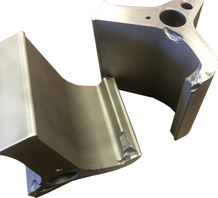
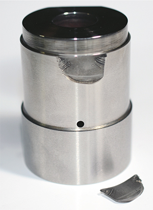
Collect samples—The failed die component (broken, twisted, bent, galled, chipped, scored, etc.) is the primary failure sample because it either is the failure site, or it contains the failure site. Also desirable: a sample part of a similar component which has not failed, preferably one that has run successfully in production. When producing replacement parts in batch lots, the stamper should take a sample from the replacement-parts bin for comparative analysis.
Compile background data—Time spent collecting background data proves vital to the success of any failure analysis. Your technicians should have a thorough understanding of the entire manufacturing process and the service histories of the failed component(s). They should reconstruct, as much as is possible, the entire sequence of events leading up to the failure.
Getting acquainted with the manufacturing process may require the investigator to obtain die-detail drawings, technical specifications, component process-flow diagrams and all relevant fabrication information. This includes the die materials used, machining methods employed, heattreatment-process parameters and surface-treatment data, including the application methods.
The ability to accurately complete a service history will depend on how detailed the recordkeeping was in the plant prior to the failure. In collecting service histories, environmental details prove particularly important. These include normal and abnormal loading, accidental overloads, cyclic loading, in-process temperature variations and die-grinding and sharpening practices.

 Video
Video