Peter Ulintz
Die-Set Guiding Systems
April 1, 2015Comments
The upper and lower halves of a stamping die must be accurately aligned and guided throughout their working distance to ensure that they perform as designed. Many dies rely solely on guide posts and bushings; others may use wear plates or a combination of wear plates and guide posts to align the upper punch and the lower die assembly.
Two basic types of guide-post and bushing systems are available:
Plain-bearing post and bushing arrangements are commercially available in either pressed-in or demountable designs. The guide post is usually—but not always—mounted to the lower die half. It will be long enough to ensure adequate engagement with the guide bushing, which is mounted in the opposite half of the die assembly, during initial contact between the tooling and the workpiece.
Plain-bearing bushings are available in several different materials, with bronze-plated steel or solid-aluminum bronze—with or without self-lubricating graphite—being most common. The post and bushing arrangement is designed with a small amount of running clearance between the post and bushing. 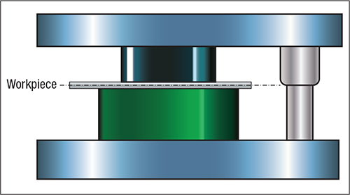
The guide bushing should engage the post at the working level of the die.
A ballbearing guide-post and bushing combination is the second type of system. Ballbearing guide components work in a preloaded condition with a rolling press-fit or negative clearance. These components simplify assembly and disassembly of long progressive die sets. However, when the stamping process produces excessive side-loading on a tool, ballbearing guide components may not be the best option. These side loads transfer to individual ballbearings that are in point-contact (tangent to the ball diameter) with the post and bushing. As a result, the balls can dig tracking marks into the guide-post OD or bushing ID.
Important Considerations for Post-Guided Systems
The guide bushing should engage the guide post at the working level of the die whenever possible (see illusration). This loads the guide post in a shear condition—its strongest condition—and imparts little or no bending moment that can cause the guide post to deflect, resulting in misalignment between the upper and lower die halves.
Oftentimes the bushing is placed much higher than the work, out of convenience or to eliminate the cost of welding and machining a mounting boss. Avoid this poor design practice.
The guide post should bypass the end of the guide bushing with the die closed. This ensures uniform wear along the entire length of the bushing. The guide pin should bypass the bushing at least ¼ in. past lead angles.Keep guide-post length to a minimum. Conditions that provide the shortest guide post, while satisfying all of the functional requirements of the die, provide the best design. When working within commercially available sizes, choose the shortest guide post that will provide the desired engagement and bypass.
Ballbearing guide components must work in a preloaded condition. The amount of preload varies with the manufacturer, but it could range from 0.0001 to 0.0021 in. Sometimes the amount of preload may be increased slightly with larger-diameter guide posts.
Excessive side loads on ballbearing guide systems can cause ball tracking. Ball tracks are physical grooves formed into the post, bushing or both. Tracking lines on one side of the guide posts or bushings can indicate the presence of high side loads.
For proper post, bushing and cage selection, operating conditions of the stamping die must be taken into consideration. Factors such as press speed, shut height, stroke length and the desired guide-post engagement with the bushing must be considered.
Types of Ballbearing Guide-Post Engagements
The first type of ball-cage engagement ensures that all ballbearings remain in constant contact with the guide post and bushing throughout the entire press stroke. In essence, the post, ball cage and bushing never disengage. This arrangement is ideally suited for high-speed, short-stroke dies.
The second type of engagement ensures that the ball cage never leaves the bushing; however, the guide post is designed to disengage the bushing at the top of each press stroke. This assembly is preferred when the elimination of pinch points is desired. An added benefit is that foreign matter cannot enter the assembly and damage the components.
The third type of engagement is designed so that the component assembly totally disengages from the bushing. This type of engagement may be the only workable solution for long-stroke applications.