Peter Ulintz Peter Ulintz
Technical Director

Understanding Formability Results

September 1, 2014
0
Comments


Process-modeling software makes science-based manufacturing knowledge readily available early in the product-design and process-quotation phases. Modeling techniques routinely employed for metal stamping often are referred to as metalforming simulation or virtual stamping. Designers select from two basic types of solvers (methods) for process modeling: one-step solvers and incremental solvers, each having unique advantages and disadvantages.

Puckering in a safe zone
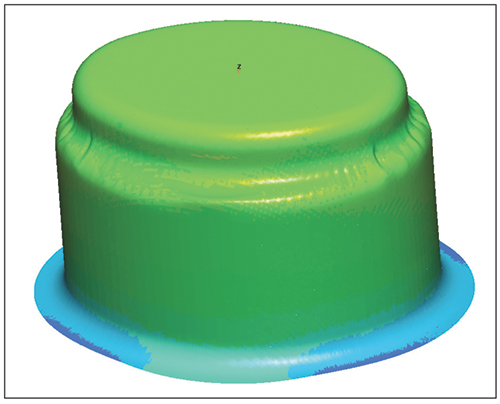
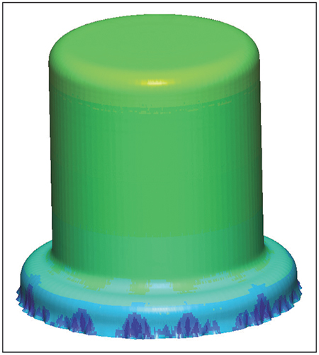
 Fig. 1—Puckering in a safe zone
One-step solvers, generally used during product development, process planning and quoting, primarily find use for assessing manufacturing feasibility. Incremental codes are used as final validation for completely defined product and process designs.

Capability and Limitations

Estimating engineers can take advantage of blank-prediction software, a derivative of the one-step method that provides users with a fast and accurate method for developing blank shapes, blank nesting and cost estimating. These solvers can capture sheetmetal stretching and compression that normally occurs during the forming process, but which may not easily be accounted for using classical length-of-line measurements or unfolding software.

The primary disadvantage of a one-step solver is that it works only for single-step forming operations. Due to simplifying assumptions, one-step codes compromise accuracy for the sake of time. But the advantage is that engineers can evaluate numerous what-if scenarios, in a matter of minutes, to help identify important process parameters. Because of their speed and minimal input data, one-step codes routinely find use for evaluating product designs and for establishing feasible processing methods when little or no process data is available.

Unlike one-step codes, incremental codes are not restricted to a single forming operation. Modeling all of the process steps allows strains generated in previous forming operations to be carried over to subsequent operations. This is important because strain history plays an important role in formability accuracy and springback prediction.

Failure using material thickness for clearance
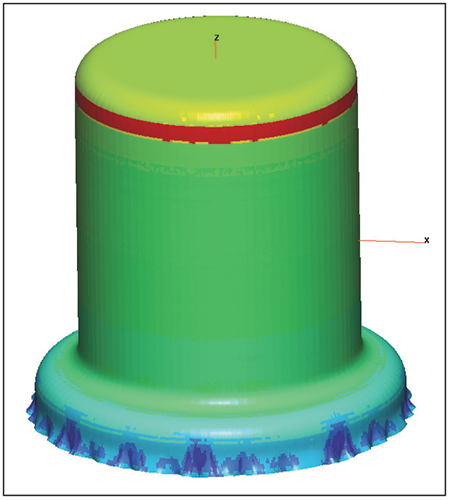
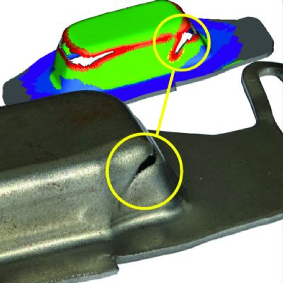
Fig. 2—Failure using material thickness for clearance
The advantage of incremental solvers is that they can be used to conduct a series of virtual die tryouts using specific blank shapes and material properties with production-intent tooling geometry. In addition to formability assessment, designers use incremental solvers to conduct trim-line optimization, springback analysis and process-sensitivity studies.

On the other hand, incremental solvers inherently are more sophisticated, requiring longer learning curves, more preprocessing steps and much longer computing time compared to one-step methods. Depending on process complexity and available computing power, this can take as long as a day or two, or as little as a few hours.

Understanding the capabilities and limitations of simulation software is necessary in order to accurately interpret formability results.

Blank-prediction software relies on simplifications for preprocessing and solving in order to minimize the required amount of input data. The software quickly provides useful blank-prediction results, but sacrifices formability accuracy for ease of use and cost-effectiveness.

Fig. 3—Success using thickening profiles for clearance
One-step codes are fast and easy to use. All they require from the user are final product geometry, usually in 3D CAD format, and minimal material properties, but more process data can be input compared to blank prediction software. The software takes the final product geometry and forces it into a flat blank. Resulting strains are calculated based on how much the material has moved, and then are mapped back onto the original product geometry.

If a one-step solver predicts excessive thinning or splitting failures, that does not mean the part being analyzed could not be produced in a single forming step. The flat-blank results from the one-step solver could be used as input data for incremental analysis. The process engineer then conducts additional analyses using precise blank shapes and specific material properties with production-intent tooling geometry. Since the blank profile, forming punch, die cavity, pressure pad and draw beads all are modeled for analysis, more accurate results are possible compared to a one-step solver.

A word of caution: It is not sufficient simply to achieve green results, where all thinning strains fall within the safe zone on the forming-limit diagram. Although the thinning strains in the reduced diameter fall well within the safe zone (Fig. 1), the material still puckers when deformed into the smaller ellipse. One-step solvers cannot detect this phenomenon, and not every incremental code can visually depict this type of defect.

Modeling the tooling geometry for incremental analysis requires great care and understanding of the forming process. Fig. 2, for example, indicates a failure near the bottom of the deep-drawn cup. An inexperienced analyst might assume that the part cannot be drawn to this depth, based on the failure. However, an analyst who understands that the flange of a deep-drawn shell will thicken as the blank diameter is reduced would provide additional clearance between the punch post and the die cavity.

The cup in Fig. 2 was produced from an austenitic stainless steel, which can thicken as much as 40 percent per side at the open end of the drawn shell. The analyst needs to modify the virtual tooling (in the computer) to provide material-thickness clearance plus an additional 40 percent per side at the die opening. This additional clearance gradually tapers back to sheetmetal thickness per side near the bottom of the cup. Reiterating the forming process with this modified tooling configuration produced the results shown in Fig. 3.

Accurate interpretation of formability results requires an understanding of the simulation-software capabilities and limitations, the metal-stamping process and tooling design. Otherwise, you’ll never know if you should believe what you see…or not. MF
Industry-Related Terms: Austenitic Stainless Steel, Blank, CAD, Die, Flange, Forming, Nesting, Stainless Steel, Thickness, Draw
View Glossary of Metalforming Terms

Technologies: Software

Comments

Must be logged in to post a comment.
There are no comments posted.

Subscribe to the Newsletter

Start receiving newsletters.