


 Stuart Keeler
Getting a Grip on Friction
February 1, 2014Comments
Let’s visit a press shop, where a stamped part is creating problems with excessive localized thinning in several locations (lack of surface area) and dimensional variations (elastic stress springback patterns). Everyone points to the culprit—a poor lubricant. Workers are hauling out buckets of different lubricants from the storage shed and each is tried in turn.
Good action plan for a successful solution? Not really. The root cause: a change in friction, and the lubricant is only one component.
Three major components contribute to the successful forming of a stamped part: the die, lubricant and workpiece material (Fig. 1). Each has an interactive role in transforming a flat blank into a complex stamping. The goal is to move the correct amount of material across the die to the specific area of the stamping undergoing deformation. All three components must make their respective contributions, yet only one—the lubricant— often receives the blame for problems and failures. Instead, the same lubricant can be found in areas with high friction (special die-design features) and low friction (material coatings). Fig. 2 (from retired GM researcher Dr. Harmon Nine) illustrates part of the problem. Friction results from three interacting inputs: die surface topography (morphology), lubricant and material surface topography. Sketch A shows the upper die and lower sheetmetal surfaces having a rough topography (high micro-in. values). The tangle of spikes attempting to slide past each other hinders material movement, and liquid lubricants will not overcome this problem. Sketch C is the reverse, with two smooth surfaces squeezing the lubricant out of the interface. The surfaces will heat up and the resulting dry surfaces will start to gall and then score. The ideal combination: sketch B, with one smooth surface to allow spikes of the mating surface to easily slide. The rough spike surface brings the lubricant into the deformation zone where it can assist the sliding. Normally, sheetmetal for exposed surfaces are rough: 25 to 50 micro-in. roughness and 100 to 150 peaks/in. The die should have the smooth surface. If the material being formed is smooth (a polished surface), then the die needs a rough surface. Even with a normally rough sheetmetal surface, friction may be too low to prevent excessive material stretching and thinning. To correct this thinning, the milled surface roughness can remain on the final die. The interaction of the two surfaces with some increased rough topography could increase the friction sufficient to restrict material flow. Highly polished dies may look great, but they are not optimum for forming some stampings. COF
This interaction of the three components (Fig. 1) results in the coefficient of friction (COF). To correctly measure COF, two of the three components must remain constant throughout the tests. Measuring the lubricant COF requires all lubricants be statistically tested in random sequence with the same die and workpiece material during the same test sequence. Even with the same die and sheetmetal, five lubricants cannot be measured with one of the lubricants tested each day for five days. Changes in room temperature, humidity, operator, die wear, location of material sample in the coil and other variables can bias the results. A lot of steel is temper-passed to eliminate yield-point elongation and apply a consistent shot-blast pattern on the steel surface. Bare steel, hot-dipped coated and galvanealled steels usually receive the same degree of temper passing. In one statistical set of draw-bead COF tests, these surfaces had values between 0.10 and 0.15. Electrogalvanized coatings do not receive a temper pass after coating and have COF values between 0.08 and 0.35 depending on the coating line. These COF differences can affect strain distribution and forming severity. Some press shops have personnel that like to replace or modify lubricants at every opportunity. Consider, for example, a metalformer experiencing constantly changing strain patterns and final stamping dimensions from one press/die throughout the day. It applies lubricant through four sprayers aimed at the die cavity before placing the blank, and then applies lubricant to the blank before the die closed. The sprayers receive lubricant from a reservoir alongside the press. A troubleshooting team notes large changes in the spray density during the shift. Secretly, the team takes hourly samples from the reservoir and measures the lubricant’s solid density. During the shift, density varies between 25- and 70-percent solids. Some of the employees believe that the lubricant is too thick, so they’ve been adding water, while others believe the lubricant is too thin and have been adding random amounts of solids. To avoid such elusive problems, the team should install a huge lubricant reservoir inside at the back end of the plant, with piping running from the reservoir to all areas of the press shop and then to each press. It should use the same lubricant for every stamping, and not trust anyone—locate the fill pipe outside in back of the plant and lock the cap. The lubricant suppler can then fill its tanker truck with the proper ratio of solid and water—only the delivery driver has the key to the filler cap. “A single lubricant should be selected for use in a press shop. The control of metal flow should be dependent on the design of the tooling, the blank size and contour, the binder force, and the draw beads. A change in the lubricant, much less a dab of lubricant on the blank, should not be the method to modify material flow within the tooling.” Technologies: Quality Control
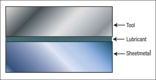
Fig. 1—Three components contribute to the coefficient of friction.
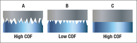
Fig. 2—Surface quality of the workpiece material and the die can come in three combinations. Only combination B will provide the lowest and most robust coefficient of friction.
View Glossary of Metalforming Terms
Comments
Must be logged in to post a comment. Sign in or Create an Account
There are no comments posted. Materials
Brinell, Rockwell and Vickers Hardness Testing: Use and Misu...
Daniel Schaeffler Friday, April 1, 2022
Troubleshooting Sheet Metal Forming Problems, Part 2: The St...
Daniel Schaeffler Friday, February 26, 2021
 Quality Control
Cobot Setup Offers Pick-and-Place for Material and Product S...
Wednesday, April 29, 2020
 Video
Video  Quality Control
Tensile Testing Part 1: Equipment, Samples and Procedures
Daniel Schaeffler Wednesday, April 29, 2020