Peter Ulintz Peter Ulintz
Technical Director

The Influence of Material Type on Die Design

November 30, 2013
0
Comments


The raw material type and grade specified for a metal stamping greatly influences the die design and build processes, so much so that some rule-of-thumb guidelines followed by die designers and toolmakers may not als apply. For example, while die designers and toolmakers typically apply a die clearance of 10 percent per side for cutting and punching mild steel, it is the worst possible clearance to apply to stainless steel in terms of burr height (Fig. 1).

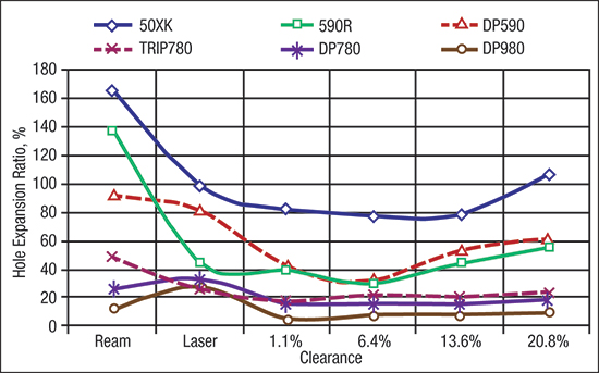
Materials with low yield-to-tensile strength ratios, such as many high-strength steels, require greater punch-to-die clearance to provide the mechanical leverage required to break the slug cleanly with a minimum burr. Recent research on advanced high-strength steels reveals that a clearance of as much as 21 percent per side may be required for optimum edge-stretching ability (Fig. 2).

Aluminum Stampings

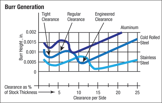
Fig. 1—Burr height and cutting clearance relationship—courtesy Dayton Progress.
Aluminum stampings weigh one-third that of comparable steel stampings of the same thickness, making aluminum an attractive material for mass reduction. However, many automotive grades of aluminum will form much like a 100,000-PSI yield-strength steel, with only about two-thirds the stretching ability. Because of aluminum’s planar anisotropy and forming limits, successfully stamping these alloys depends highly on blank shape. Part design characteristics, including radii, draw depths, wall angles, steps and transitions, all interact to affect the cost and quality of an aluminum stamping.

Draw-reduction ratios for cupping will vary depending on the aluminum grade being formed. Some grades can have a limiting draw ratio similar to that of steel, while others will be lower. Many die-design handbooks contain draw-reduction tables for low-carbon steel. Due to differences in workhardening behavior, surface topography and other factors, stampers should not use those tables for brass, aluminum or any other nonferrous materials.

For aluminum alloys, keep the limiting draw ratio (LDR) below 1.6 unless you have previous experience with the particular alloy in question. An LDR of 1.6 is equivalent to approximately 38 percent reduction for the first draw. Subsequent redrawing percentages should be approximately 22 percent, 17 percent and 12 percent, assuming that the ratio of material thickness to blank diameter exceeds 0.25.

Set punch radii for aluminum stampings at eight to 10 times material thickness, and die entry radius at five to 10 times material thickness. As a general rule, the punch radius should exceed the die radius, to reduce the tendency for the punch to penetrate through the material.

Stainless Steel

Fig. 2—AHSS edge stretch and cutting clearance relationships, Konieczny and Henderson, 2007.
Compared to mild steels, forming stainless steels requires more press power and energy (often twice as much), due to their high workhardening rate. Blankholder (draw pad) pressure requirements will be much higher than with low-carbon drawing steel. Ferritic grades such as Type 430 stainless steel require about 50 percent more pressure, while the austenitic grades such as Type 304 and 316 may require as much as three times the force of low-carbon steel.

High forming pressures and frictional heat require slower drawing speeds than with low-carbon steel. A unique feature when cold-forming stainless steels: severe deformation is possible when using slower forming speeds. This differs from plain carbon steels, which form virtually the same regardless of forming speed. In general, when forming stainless steel into difficult shapes, slow down.

Although stainless-steel draw-reduction ratios are similar to those for plain carbon steels, the required clearances between the draw post and die cavity wall may need to be greater for stainless steels. Austenitic grades require a clearance of sheetmetal thickness plus an additional 35 to 40 percent, while most ferritic alloys require sheetmetal thickness plus 10 to 15 percent additional clearance.

Copper and Copper Alloys

Formability of copper and copper alloys, such as bronzes and brasses, depends greatly on alloy and temper. Some alloys can display significant directionality after rolling, such as C51000 phosphor bronze. Bend directionality affects part layout in the strip.

Stampers achieve the deepest draws with alloy C52100, followed by the brasses, in order of decreasing zinc level. The LDR of cartridge brass increases with grain size.

Nickel and Cobalt Alloys

Generally, 30 to 50 percent more power is required to form nickel alloys compared to forming low-carbon steels. High-cobalt or tungsten alloys may require 50 to 100 percent more power.

For superior surface finish, stampers opt for soft die materials such as aluminum bronze, nickel-aluminum bronze and zinc alloys. Radii, fillets and clearances usually are larger than those for brass and steel. MF
Industry-Related Terms: Alloys, Blank, Brass, Burr Height, Burr, Die Clearance, Die, Draw, Drawing, Edge, Ferritic, Form, Forming, Phosphor Bronze, Slug, Stainless Steel, Surface, Thickness
View Glossary of Metalforming Terms

Technologies: Quality Control, Tooling

Comments

Must be logged in to post a comment.
There are no comments posted.

Subscribe to the Newsletter

Start receiving newsletters.