What Chacko is alluding to is Dallas’ ServoPressSelect feed control, slated for release by year-end. He says the control will allow servo-press users to select from among five types of feed profiles to match the variety of tasks that a servo press can perform.
“ServoPressSelect is an offshoot of our ProfileSelect (introduced in 2010),” explains Dallas president Joe Gentilia. “The idea is to minimize the stress imparted on the feed’s servo drive and mechanics, by creating a feed speed and acceleration profile. We look at the time available to feed and design the motion profile—slowly accelerate to feed speed, and then decelerate—to that allotted time.”
The five profile types available:
• Sinusoidal
• Triangular
• Trapezoidal with three equal motion segments
• Trapezoidal with 1/4-1/2-1/4 motion segments
• Electronic gearing
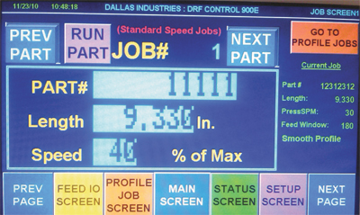
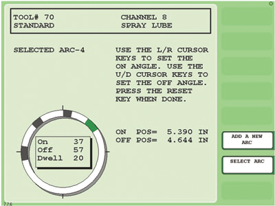
As a result, the human-machine interface (HMI) of the new control looks different than that for the standard feed control. In place of feed speed (as a percentage of maximum), the control needs to know feed time (in msec.) and the motion-profile type.
“Most stampers use the sinusoidal profile,” says Gentilia, “gradually ramping up feed speed during the first part of the feed cycle, then ramping down from peek speed at the end of the cycle. But stampers, as they become more familiar with the flexibility and opportunities afforded by servo presses, will realize some definite opportunities to use other profiles.
“For example,” Gentilia continues, “a more aggressive motion profile (triangular or trapezoidal) will allow higher run rates or other applications where there’s minimal time to index. And the added acceleration with these profiles also can help if you want to kick the part off the end of the die.”
Ramp up the Dialogue
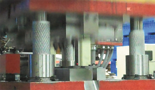 |
| This screen capture from digital video footage of a servo-drive press in action, provided by Anchor Danly’s Ray Osborne, illustrates what can happen to ball-bearing cages when the ram accelerates rapidly from BDC and then reverses quickly from TDC. At this point in the stroke, the ram is rapidly accelerating downward just milliseconds after TDC. The cages have lost their timing and position, ultimately leading to performance problems and eventual damage to the retaining hardware. |
Coe’s controls engineering manager Bruce Grant notes that the firm has installed a handful of its ServoMaster feeds onto servo presses in the last few years, and says that the time is now for stampers, press builders and feed suppliers to ramp up the dialogue on servo-press applications. Including gaining some understanding of how the presses will be used in the future. “This is a major shift in the process that affects everything going on under the ram,” Grant says. “We have several servo-press projects under for the second half of 2012 and into 2013, many of which we are addressing with our standard servo-feed control. But for the larger transfer-press applications, we’re going with a more flexible controls package—PLC-based with motion-drive networked packages customized to the feed-line automation and indexing process.
“The challenge going forward,” Grant continues, “is how do we build into these projects the ability to index the material with more agility and in a more timely manner, given the unknowns regarding what the customer may need down the road? We’re addressing today’s applications, but what’s coming?”
Remove the Word ‘Unformable’ from your Vocabulary
For many, what’s coming is already here.
“Some stampers are solving some previously unsolvable application problems thanks to the flexibility afforded by servo-drive presses,” says Jim Finnerty, product manager for Wintriss Controls LLC. “They’re forming materials once considered unformable, and making a lot of money as a result.
“We’re seeing applications being developed where secondary operations are now being done under the ram,” Finnerty continues, “since different portions of the forming cycle require different ram velocities—possible with servo presses. And we’re seeing servo-press applications where stampers are using the technology to vary the cam timing action to very creatively perform work on the sides of parts.”
Conventional timing methods used for flywheel/clutch-driven mechanical presses, where everything happens in a repetitive cycle through a complete revolution, will not work with servo presses. The activities in the press cell—feed, part off, etc.—all happen in a repetitive cycle with a conventional press, but with a servo press this might not happen.
“As a result, we only want to activate timing outputs at certain stages,” says Finnerty, “and activate or monitor sensor inputs at other stages. So, for example, we may only feed the first stage of the cycle, activate cutoff on the last stroke and look for part ejection on the final stage.”
Three Basic Uses, Three Control Modes
Finnerty observes that stampers are using servo-drive presses in three different s: Either they bought the press to:
• Make it act like several different presses—short-stroke high-speed, longer-stroke slower-speed or some combination. Versatile but conventional.
• Use it like a hydraulic press; or
• Take full advantage of flexibility and variable programmability.
Due to this wide ranging application of servo presses among metalformers, Wintriss developed the SmartPac 2 Servo edition. While the traditional edition of the press control is resolver based—“we drive a resolver with the crankshaft, and run our timing off of that,” Finnerty says—with a servo press that approach won’t work. In place of the resolver, then, is a precision linear sensor used to monitor ram position throughout each stroke. This allows the control to operate in any of three selectable built-in motion curves, designed to accommodate the three press functions described above. The three motion curves:
• Sinusoidal—closely approximates the operation of a standard part-revolution press.
• Proportional—closely approximates the motion of a hydraulic press, with equal timing-adjustment increments throughout the stroke.
• Asymmetrical—offering high-resolution programmability near the bottom of the stroke.
“Within the asymmetrical and most flexible motion curve, we programmed three variable-resolution curves into the control,” says Finnerty. “All of the curves are proportional through the top of the stroke, but then feature high-resolution areas near the bottom. This allows a stamper to set sensor-monitoring windows or time limit switches to very small increments (as small as 0.001 in. of slide motion on a 2.5-in. stroke).”
The control can monitor and direct as many as 10 stages of slide motion, although Finnerty says even the most complex jobs experienced so far have required control of only five stages (defined as a change in slide direction, not speed).
“Lastly,” adds Finnerty, “the control is self-learning, enabling it to capture the motion profile for a job when operating in the ‘learn mode,’ and storing the data as part of a part recipe.”
No need for the operator to enter parameters for each program—which can become quite complex for servo-press applications.
Obey the Speed Limit
For a final word on the new-found speed and flexibility arriving with the move to servo-drive presses, we spoke with Anchor Danly’s Ray Osborne, director of engineering for the maker of die sets and precision components. While total control of the ram and the ability to “do things that you can’t do in a conventional mechanical press can take stampers in directions never before experienced,” says Osborne, he also sounds a note of caution.
“Everyone thinks that once the press moves off of bottom-dead center (BDC),” Osborne says, “that the work is done. But the rapid upstroke acceleration and velocity from 180 deg. to top-dead center (TDC) can seriously impact the performance, over time, of a host of press-system components. In-die tapping units, cam-slide units, ball-bearing guidance systems, nitrogen systems, pad-retaining hardware and other components are potentially in jeopardy.”
To illustrate, Osborne describes a servo-press installation where he recorded digital video to illustrate what can happen to ball-bearing cages when the ram accelerates rapidly from BDC and quickly reverses direction from TDC. It’s not a pretty sight.
“When the ball bearings are disengaged from the preload (during the upstroke), the ram reverses direction and accelerates downward so quickly that the cages are actually suspended in mid-air,” says Osborne. “You can see it on the video. The cages immediately lose their timing and position. In this scenario, the ball bearings are forced into a ‘skid’ condition, causing the guide components to overheat and eventually scoring the guide pin and bushing.”
There are options for dealing with this condition, explains Osborne, in particular changing the length of the guide pin or bushing to ensure the ball bearings unload as close to TDC as possible. Or, the stamper can select a combination of components that ensures some bearings are als under preload—commonly referred to as Type 1 operation. But, as many stampers know (particularly those working in the high-speed canning industry), Type 1 operation often can lead to a phenomenon called “cage creep.” This, explains Osborne, refers to the tendency of a rolling-element retainer cage to gradually deviate from its nominal TDC and BDC positions. Certain measures must be taken to guard against cage creep.
Help is on the
As described above, equipment suppliers must find s to support stampers that take the leap to servo-drive presses. And guide components are no exception. To address the retainer-cage issue described by Osborne, he told us of a patent-pending prototype guidance system Anchor Danly has in field testing that prevents the cage from ever being in freefall.
In light of this pending solution, Osborne simply suggests that stampers developing procedures for servo-drive presses be mindful of any rapid acceleration from BDC. Instead, they should gradually accelerate to full speed on the upstroke, over 10 to 20 deg. of ram motion. He explains additional reasons why this makes for sound practice:
“With cam-slide units, after the work has been done and the press is on the upstroke, you’re sometimes at the mercy of the cam’s slide-return system,” Osborne says. “Stripping force is critical; give the springs enough time to work. Upstroke too quickly and you can prematurely wear, or even break, punches. Yes, this can occur in a conventional press, but the situation is exacerbated with a servo-drive press and the temptation to crank up the speed after BDC.
“The suggestion is to wait until the cam completely disengages and the tooling completely extracts before hitting the accelerator,” Osborne continues. “Then go ahead and accelerate up. The same holds true when performing in-die tapping. When you rapidly accelerate up from BDC, you place additional undue strain on the mechanism.”
Final warning: Enjoy the exciting, winding road that servo-drive presses will lead you down, but from 180 to 360 deg., watch that speed limit. MFIndustry-Related Terms: Blanking,
Cam,
Center,
Coining,
Die,
Drawing,
Form,
Forming,
Hardware,
Hydraulic Press,
Laser Welding,
LASER,
Masking,
Nominal,
Point,
Prototype,
Ram,
Run,
Stroke,
TappingView Glossary of Metalforming Terms
See also: Wintriss Controls Group LLC, Coe Press Equipment Corporation, Dallas Industries, DAYTON Lamina Corporation
Technologies: Coil and Sheet Handling, Pressroom Automation, Stamping Presses


 Video
Video