


 Peter Ulintz
Material Gainers
September 1, 2011Comments
The metal stamping shown here (Fig. 1) is splitting in a highly strained area. The problem occurs intermittently and unpredictably during production, causing the stamper to experience excessive machine downtime and high die-maintenance costs. The manufacturing team concludes that the stamping process lacks robustness, since small changes in material properties, lubrication and restraining forces contribute to the necking and splitting issue.
After careful consideration, engineers decide to add material gainers—embossments in the blank that help to more uniformly distribute strains (Fig. 2). This is accomplished by increasing the local length of line in the problem area. The increased length of line then is displaced into the critical area as the stamping forms; eliminating the splits.
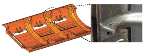
Fig. 1
When forming a material gainer, the stamper must ensure that the edge of the blank does not “draw-in” when forming the embossments. Otherwise, there will be minimal increase in the length of line.
But how large should the material gainer be? Should it be round, elliptical or some other irregular shape? If the shape is irregular, how should it be oriented in the blank? How deep should it be formed? Where should it be placed in the blank so it ends up in the right place after forming? Since the material will be thinner in the embossment due to stretching, won’t it be more likely to split?
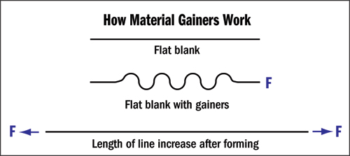 |
| Fig. 2 |
Imagine the amount of trail and error required to answer all of these questions. The process could take days, even weeks. Fortunately, computer forming simulation can be used to quickly provide the answers.
Without a doubt, the most revolutionary development in the metal-stamping and tool-and-die industries during the past 20 yr. has been the emergence, commercialization and mainstream use of computerized metalforming simulation. Unfortunately, many die-shop and stamping-company professionals believe that computer simulation is of use only for new tool-and-die-engineering activities. Contrary to this belief, computer simulation can be a powerful tool for solving press-shop problems such as the one described above.
This first thing needed is an accurate 3D model of the die surfaces. If the die design was originally verified using computer simulation, die-surface models may already exist. However, one should proceed cautiously when using design-verification models for problem solving. These models are created long before the die is actually machined, built or tried out. Often, the production-die surfaces will differ considerably from the CAE models, especially if problems existed during die tryout.
To ensure accurate modeling of the production process, scan the die surfaces in 3D to create new surfaces to compare to existing models. This can be accomplished with a CMM, white-light scanning or laser-scanning machine.
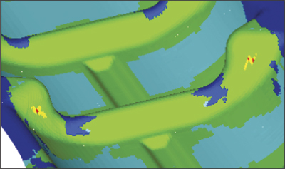 |
| Fig. 3 |
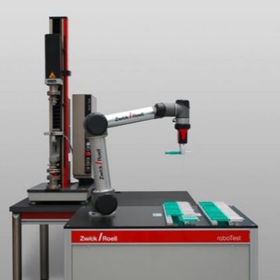
The next step is to accurately model the production material properties. All commercial simulation software will feature material libraries containing generic material models. These models usually represent typical or nominal properties for a given material type. When troubleshooting problems in the press shop, engineers must obtain actual material properties to ensure accurate simulation results. This data can be obtained easily and inexpensively with simple tensile tests.
Having obtained accurate die-surface data and material properties, computer simulation can occur. The initial results for the problem part (Fig. 3) nearly match the failures we see in the actual stamping. Since the simulation model now matches our real-world results, we can begin to develop the material gainers.
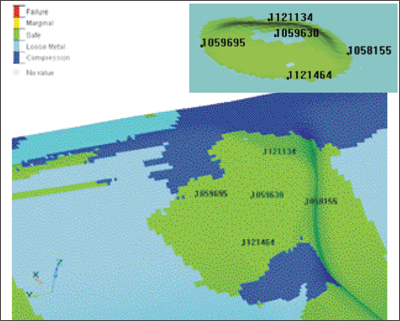 |
| Fig. 4 |
Establishing gainer size and locations will require some trial and error. The best to track results is to identify a few nodes on the blank using the finite-element mesh. In this instance, five nodes were identified. The nodes are tracked during forming simulation until achieving the desired results—no failures (Fig. 4).
The five nodal locations chosen allow the gainer to be accurately described. The height, shape and angular location can be determined and the data passed to engineering and the toolroom. Since the initial simulation showed good correlation between the computer model and real-world results, the die maker can proceed with a relatively high level of confidence. MFView Glossary of Metalforming Terms
Technologies: Quality Control, Software
Comments
Must be logged in to post a comment. Sign in or Create an Account
There are no comments posted. Materials
Brinell, Rockwell and Vickers Hardness Testing: Use and Misu...
Daniel Schaeffler Friday, April 1, 2022
Troubleshooting Sheet Metal Forming Problems, Part 2: The St...
Daniel Schaeffler Friday, February 26, 2021
 Quality Control
Cobot Setup Offers Pick-and-Place for Material and Product S...
Wednesday, April 29, 2020
 Video
Video 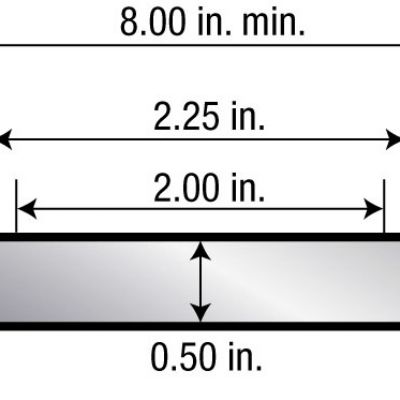 Quality Control
Tensile Testing Part 1: Equipment, Samples and Procedures
Daniel Schaeffler Wednesday, April 29, 2020