David Smith David Smith
President

Die Timing to Control Snapthrough

November 1, 2011
0
Comments


The loud “boom” heard when sheetmetal is punched or results from the release of snapthrough energy. This can cause broken crankshafts and the failure of other press components. This article covers simple die-timing adjustments that stampers can make to control snapthrough; severe cases may require the installation of hydraulic dampers.

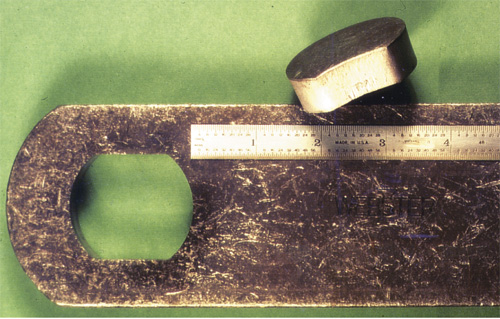
Fig. 1—A chain sidebar of 0.625-in. SAE-ASTM 1039 fine-grained carbon steel.
Another technique to control snapthrough is to reduce the peak pressure required to cut through material, by grinding one or more shear angle(s) on the punch or die. If the cutout, such as a slug, is discarded, the shear is placed on the punch. Punch length adjustments also can be made.

Waveform Signature—a Case Study

The task here (Fig. 1) involved press-damage control on a severe punching operation. Shown is a large chain sidebar fabricated of 0.625-in.AISI-SAE 1039 fine-grained carbon steel (a 6-in. scale is shown for size comparison). The punch has a pointed angular shear optimized for the task.

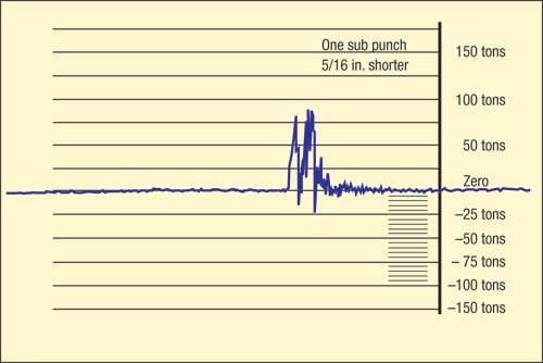
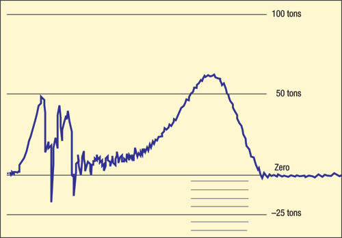
Waveform signature analysis (Fig. 2) provided a to measure die-timing opportunities to reduce the destructive negative reverse load on the press. Shown is the waveform signature of the stress-strain relationship when cutting off and piercing two holes in the part. The data was taken with a chart-recorder speed of 8 in./sec.; the vertical axis indicates strain or force, the horizontal axis represents time.

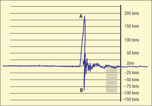
Fig. 2—This chart recording displays the waveform signature of a combined punching and cutoff operation, and points to excessive snapthrough (or reverse load).
The press speed of the waveform signature is 60 strokes/min. Even at a chart speed of 8 in./sec., the waveform trace distance from initial contact of the punch on the workpiece until it breaks through is very short. The portion of the waveform from initial punch contact to breakthrough occurs in 0.20 in. of chart travel, or 25 msec.

Energy Analysis

The punching waveform exhibits a sharp negative spike below the zero trace at breakthrough. This results from the sudden release of the energy stored in the press and die in the form of strain or deflection. The magnitude of the actual energy released increases as the square of the actual tonnage developed at the moment of final breakthrough.

Here’s a simplified mathematical analysis. To calculate the actual energy developed:

E = F × D/2

F = Pressure at moment of breakthrough, short tons (lbf x 2000)

D = Amount of total deflection, in.

E × 166.7 = Energy, ft.-lb.

A simplified example using American units:

If 400 tons resulted in 0.080-in. total deflection to cut through a thick steel blank, the energy released at snapthrough, from the formula: 2667 ft.-lb.

Die-Timing Improvement

Adjusting the timing of shear and punch-entry sequences, to provide a gradual release of force prior to snapthrough, offers a straightforward to reduce the shock and noise associated with excessive snapthrough. The simplified analysis of the square-law relationship can be applied to our case study (which took place at Webster Industries, Tiffin, OH). Note: Advice was provided by control-system manufacturers Toledo Integrated Systems, Helm Instrument Co. and, Link Systems.

A 300-ton straightside press was used for this operation. The allowable reverse load is 30 tons—point A of Fig. 2 illustrates a peak load of 191 tons, well within press capacity. The reverse load (B) is 87 tons, nearly three times the allowable amount. The die was immediately taken to the repair bench and one punch shortened by 0.312 in. Balanced angular shear was ground on the punches and the parting punch.

Careful timing of the cutting sequence resulted in a tonnage reduction at the moment of snapthrough to 200 tons—the reduction in shock and noise proved to be dramatic, since only half the tonnage produces only half as much press deflection, or 0.040-in. The resultant snapthrough energy: only 667 ft.-lb., a nearly 75-percent reduction.

Fig. 3—Waveform signature of the operation illustrated in Fig. 2 after modifying the die by adding timing and balanced shear.
Fig. 3 illustrates the improvement achieved by modifying the tool. Peak tonnage dropped to 82.8 tons, less than half the initial value, and reverse load dropped to 22 tons, about one-fourth the former value.

This example, and the documented results of many other tests, show snapthrough reductions conforming closely to the square-law formula. Simply stated, if the amount of force or tonnage released at the moment of punch breakthrough can be reduced by one-half, the amount of stored energy, which causes snapthrough problems, will be reduced to one-fourth the former magnitude.

Importance of Breakthrough Timing

In timing punch entry (or die shear), stampers must take care to provide for a gradual release of the developed force. With the exception of high-speed applications, a shock load typically is not generated by the impact of the punch on the stock. In fact, when the punch first contacts the workpiece, the initial work may be done by the kinetic energy of the slide. To complete the work, the flywheel or hydraulic pump supplies energy. As this occurs, the press members deflect.

An analysis of the quantity of energy involved will show why a gradual reduction in cutting pressure prior to snapthrough is critical. A general rule for snapthrough (or reverse load) that a press can withstand without sustaining damage is 10 percent of rated press force or tonnage. Reverse loads significantly higher than 10 percent of total capacity may damage the machine. Particularly critical is the slide connection—the attachment of the pitman to the slide. Should this connection fail, the slide may fall unexpectedly.

Some presses are designed to withstand higher reverse loads. For example, manufacturers can supply presses designed to withstand repeated reverse loads of 50 percent of rated capacity or more.

Fig. 4—The waveform signatures of a combined punching, cutoff, and joggle bending operation.

Fig. 4 illustrates the waveform signature of a combined punching, cutoff and joggle-bending operation. Here, AISI-SAE 1039 steel 0.500-in. thick by 2.0 in. wide has two holes punched, and a 0.562-in. joggle formed. The part, an engineering-class chain sidebar, also is cut off in this combined operation.

The die is correctly timed, and snapthrough energy release is well below10 percent capacity of the 300-ton straightside press used for the operation.

Technique for Die Timing

In addition to providing angular shear on the punch and die, the entry of individual punches may be timed to reduce cutting forces. In most cases, the punches penetrate one-third of stock thickness, when rapid plastic yielding (fracture) occurs. Therefore, the entry of the punches usually is stepped in increments of approximately one-third stock thickness.

Tighter-than-needed die clearances increase cutting forces and snapthrough energy. Good tool-engineering practices allow the process to determine the clearances used rather than following arbitrary rules. Some mild-steel jobs work best at 18 percent side clearance, while others (such as hard brass) require very little clearance to avoid a shaving operation. This analytical tool is valuable to optimize processes.

Optimizing punch and die shear, together with stepping punch entry, can reduce peak cutting dramatically. It is important to note that the total flywheel energy required per stroke is not reduced.

The process of optimizing cutting forces can be aided by the use of force monitoring and waveform signature analysis. These methods are valuable process-control tools.

Applying This Technology

Metalformers should keep records of die timing, and note the optimum die timing for each job. This information will avoid trial-and-error work when a die is resharpened. Proven timing data also proves invaluable for adjustment of new dies.

Nearly all tonnage monitors start with a DC signal converted for a digital signal for display and remote communications. A chart recorder uses the DC signal obtained from a connector on the monitor. MF
Industry-Related Terms: Bending, Blank, Carbon Steel, Case, Die, Form, Grinding, Piercing, Scale, Slug, Stroke, Thickness
View Glossary of Metalforming Terms

Technologies: Sensing/Electronics/IOT, Tooling

Comments

Must be logged in to post a comment.
There are no comments posted.

Subscribe to the Newsletter

Start receiving newsletters.