Peter Ulintz Peter Ulintz
Technical Director

Pressure Strippers Part 1

July 1, 2009
0
Comments


The term “stripper” applies to the stripping plate, keepers or retainers, and pressure system (springs, gas, rubber, etc.), which all aid in the stripping of stock material from around the punch steel.

Most die-design rules of thumb recommend stripper pressure be equivalent to approximately 10 to 30 percent of the cutting force. In general, softer materials and tighter die clearances will require higher stripping force. But for every rule of thumb there is some degree of trade-off for the convenience of applying the rule. In the case of stripping forces, the trade off is die wear.

From a technical perspective, frictional forces influence the amount of pressure required for stripping. In high-school physics we learned, “Friction is FmN.” This was a convenient to remember that friction (F) was the product of the coefficient of friction (m) times the normal force (N). The frictional forces associated with stripping force relate directly to the rate at which the punch and die-component cutting edges wear. As a result, a primary design objective should be to reduce the value of the “m” and “N” factors so that more stampings can be produced between sharpening.

Factors that influence m include:

Fig. 1 Keeper block , spool
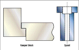
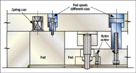
Fig. 1—Keeper and spools are more reliable than stripper bolts.

• Lubrication, which breaks down with process heat;

• Punch surface finish, which contributes to adhesive wear;

• Punch hardness, which often degrades over time due to poor sharpening practices; and

• The type of material being punched.

Factors that influence N include:

• Punch-to-die cutting clearance, which increases the normal force as the clearance is reduced;

• The ratio of hole size to stock thickness;

• The spacing between adjacent holes; and

• The cutting edge conditions on the punch.

Stripper construction plays a significant role in die reliability and durability. Here are some important design guidelines to consider:

1) Avoid stripper bolts that may become loose and also tend to break at the undercut of the threads.

2) Use keeper block or spools in place of stripper bolts (Fig. 1).

3) If the die design requires spools of more than one length, use different diameters to prevent them from being mounted improperly (Fig. 2).

spools of different lengths also should be a different size.
Fig. 2—Spools of different lengths also should be a different size.

Advantages of using keepers:

• Increased rigidity and reduced tipping due to more surface area, which provides improved guiding;

• A keeper that is correctly designed will not bend or deflect and cause jamming whereas stripper bolts bend easily;

• Keepers provide more strength under high stripping pressure whereas large strippers would require far too many stripper bolts; and

• Keepers are the best choice for long stripper plate travel due to better guiding.

Advantages of using spools:

• Reduced space required on the die shoe as compared to keepers; and

• The round shape is readily machined reducing machining costs.

4) Use spring cans around springs in every pad that bottoms out.

5) Use spring retainers to hold springs in the upper die if a pad is removed for service.

6) To get longer life from nitrogen cylinders, do not use the maximum piston travel listed in the catalog—instead, use 85 percent of rated travel.

7) Do not preload nitrogen cylinders with the pad keepers. Provide extra travel (1⁄8 to 1⁄4 in. is common) on the keepers beyond full piston extension.

8) Make the pad travel slightly more than the die work. This is required so the material does not move if there is pad bounce.

9) In progressive dies, all upper pressure pads that push stock lifters down as the die closes must have the same travel so that the strip and lifters are level as the parts locate in each station. If the strip is not level, the parts may be pulled out of location.

10) Provide windows in the face of large stripper pads so that ball lock punches can be removed easily.

11) For material that is more than 0.045 in. thick, provide pad balancers to prevent damage to the die caused by pressure pads tipping during the start of a new coil of material into the die.

12) When a pressure pad will not balance on the stock in the work stations, provide stock balancers to prevent tipping.

13) Do not locate springs over a stock balancer as they will provide no holddown force to the part being formed.

14) Remember that springs located half between a pad balancer and the material only provide one-half the spring force on the stock material.

Next month we’ll examine the advantages and disadvantages of various stripper plate designs. MF

Industry-Related Terms: Case, Die, Edge, Plate, Stripper, Stripping, Surface, Thickness, Undercut
View Glossary of Metalforming Terms

Technologies: Tooling

Comments

Must be logged in to post a comment.
There are no comments posted.

Subscribe to the Newsletter

Start receiving newsletters.