The most common configuration of a compact line, the reel feeder-straightener, gets the call when material is not excessively thick and marking of the coil OD is surface critical. A cradle is not a good choice for stampers running very thin material, say 0.016 in. thick, or narrow-width coils. Processing a lot of partial-run coils also sets the stage for using a reel, which makes rewinding the partial coil a simple task provided it’s equipped with proper coil-holddown arms. Holddown arms also keep the coil tight while rewinding, a difficult if not impossible task to accomplish with a cradle. And, stampers that run dies off center also opt for a reel, since most cradles are self-centering with little provision for off-center movement.
Having selected a reel setup, now the stamper must choose between a single- or dual-reel installation. A dual-reel system requires room on the plant floor to allow the decoilers to swing out. A single-reel setup with a coil car requires less floor space, and our studies indicate that stampers will experience little difference in coil-change time between a dual-reel setup and a single reel with coil car.
Power Options
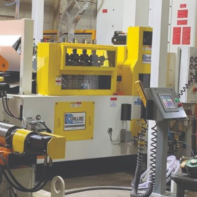
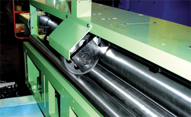
A peeler/threading table promotes
hands-free and safe coil threading into the straightener-feeder head. An extendable peeler tongue reaches the leading edge of the coil to help peel it a
from the mandrel, and the threading table pivots to assist in safely moving
the coil under the straightening rolls.
To provide sufficient power to decoil and rewind on a reel, the unit typically must include a hydraulic or a variable-frequency drive. Also, to provide enough power to expand the mandrel on the coil ID, metalformers can opt for a hydraulic-expansion feature. Mechanically, expansion is best accomplished with the use of wedges; however, this limits the expansion range. For lighter-weight coils, a linkage mechanism offers greater range but is not as robust.
Another consideration is the degree of automation required. For shops that change jobs frequently and want to eliminate the potential for operator error, an automated system may provide the best solution. Here, an operator enters a job number into the system controller, which has previously been saved, to automatically recall the parameters for a job.
When specifying an automated line, detail these parameters:
1) Feed length/progression
2) Straightener settings/straightener-roll penetration
3) Speed (strokes/min.)
4) Feed-line height
5) Traversing reel location, based on the width of the material
6) Coil-cone keeper location, based on the width of the material
7) Motorized guide rollers—entry and exit.
Meanwhile, stampers that change coils less frequently or do not require a great degree of sophistication can make do with a standard line. Specify these parameters:
1) Powered-straightener settings/ straightener-roll penetration
2) Powered feed-line height adjustment
3) Powered peeler and threading table
4) Hydraulic coil-reel expansion and rotation (for power).
With this style of feed line the metalformer obtains some level of automation, along with manual coil centering and setting of coil-keeper location. Consider the addition of a coil car to assist with locating the coil on the mandrel, which will quicken coil changes and prevent damage to the coil during loading.
When to Use Cradle-Feed Straightener Lines
Cradle-feed straightener lines offer a good solution when stamping thick and high-strength materials. Safety is of the essence—once the bands are cut, proper holddown or containment devices prevent the coil from clock-springing. With the cradle design, the weight of the coil itself helps hold the coil in place, while with a freestanding reel the stamper must use a holddown device—sometimes multiple devices—to prevent the coil from unwinding.
To quicken coil changeovers, stampers consider several options. A dual-cradle staging system allows a coil to be placed in a staging cradle directly behind the main powered cradle. As one coil winds out, an arm on the staging cradle pushes the next coil into position so that the operator need not wait for the delivery of another coil.
Another more-expensive option is a dual-shifting cradle system, which requires less overall length since the staged coil is placed in a cradle beside the running coil. When the primary coil runs out, the staged coil shifts directly behind the feeder straightener.
Choosing the cradle option, consider these application guidelines:
1) Will marking be a problem? Since the coil is driven by its OD, the stamper runs the risk of marking the material, so a cradle will not suffice when running cosmetic or polished material. However, when stamping noncosmetic parts or components that will not be seen—such as those mounted on a car or truck chassis—a cradle will suffice.
2) Do you typically run partial coils? Once upon a time, before manufacturers focused on operating just in time, many would run out an entire coil and store extra parts. Now most metalformers stop each run after stamping the required number of parts, and then remove and store each partial coil. With a coil resting in the cradle, rewinding it tightly is difficult. However, holding the coil on a reel allows the straightener head and holddown arm to work together to rewind the coil tightly so it can be safely and efficiently banded and placed back into stock.
A note about coil-containment safety: Safe coil containment requires the use the proper holddown and containment arms, particularly given the growing use of higher-strength steels. Holddown and containment arms are needed on reels and cradles to prevent the coil from dangerously unraveling or clock-springing. For higher-strength materials, use a holddown arm with a powered wheel on its end to help peel the material off of the coil and onto the threader/peeler table.
Head Designs
Some compact straightener-feeder heads include a closed-loop measuring wheel that provides feedback to the controller to indicate actual movement of the material, not just roll rotation. So, for example, if a slug is picked up in the die and the feed rolls slip on the material, closed-loop feedback from the measuring wheel can trigger an emergency stop and prevent die damage.
With the method of decoiling selected, let’s focus on the feeder/straightener-head features. Metalformers select from two basic straightener-head designs—one uses individual roll adjustment for bending the material between two opposing rolls, the other employs a bank-adjustable setup.
A bank-adjustable straightener head yields optimum flatness results. With a bank adjustment versus an individual-roll-adjusted straightener, the rolls can have a smaller diameter and be spaced more closely together. This setup bends the material more tightly around the roll radius. Also, a bank-adjustment design requires only two adjustments to the straightener-roll settings—for entry and exit gap.
Typically, the feeder/straightener head performs more work to the material at the entry side then at the exit, with the exit-side gap set at or near the material thickness. As the capacity of the straightener increases, metalformers look to add backup or support rolls to the straightener to prevent the smaller-diameter rolls from deflecting, much like the design of a precision leveler. Also, the more rolls in the bank the better the straightening results. Typical straighteners with individual roll adjust will only include only five or seven rolls. With nine or more rolls, flatness tolerance will improve and, in many cases, material defects such as crossbow can be reduced or eliminated.
To ensure sufficient power to pull the material through the straightener head, the rolls must be driven—ideally all of them, although this greatly increases the cost and complexity of the machine. Therefore, in most cases stampers can get by with a machine with driven bottom rolls.
Other Straightener-Head Features to Consider
1) Straightener-head opening option. With this important option, the head can be opened for easy access to the rolls for cleaning. This proves particularly useful to stampers that switch from forming hot-rolled scaly material to cold-rolled steel or aluminum on the same machine. This feature also eases the task of threading the start of the coil into the straightener-feeder head.
2) An effective peeler/threading table promotes hands-free and safe coil threading into the straightener-feeder head. An extendable peeler tongue will reach the leading edge of the coil to help peel it a from the mandrel, and the threading table pivots up and down to assist in safely moving the coil under the straightening rolls. Also, a coil-break arm on the straightener can help back-break the leading coil edge, if needed.
3) Some compact straightener-feeder heads include a closed-loop measuring wheel that provides feedback to the controller to indicate actual movement of the material, not just roll rotation. This proves useful, for example, should a slug get picked up in the die and the feed rolls slip on the material. Without closed-loop feedback from the measuring wheel, the feeder controller would think that the move had been made, and the die might become damaged. But with closed-loop feedback, the emergency stop can be engaged to prevent die damage.
4) Straightener-roll depth setting. Some machines will only offer mechanical adjustment and dial/pointer indicators for setting roll depth. Others will offer hydraulic motors to make these adjustments, particularly popular with stampers forming thicker, stronger materials. These settings can be saved in memory and the actual settings digitally displayed at the control panel.
5) Material guiding. This feature ensures that material feeds squarely through the straightener. Higher-quality machines will have entry and exit guide rolls, and automated versions of certain machines employ motorized rolls with settings saved for each job.
6) Pass-line height adjustment can be accomplished manually with a crank handle and jack screws—requiring quite an amount of arm power. Or, higher-end machines have hydraulic pass-line adjustment accomplished with the turn of a switch. This parameter can be saved in the control when using automated compact lines.
Machine Construction
Overall machine construction comprises the last piece of the puzzle. Some so-called compact lines actually combine servo-roll feeds with a nonpowered pull-through straightener and a separate reel or cradle. This, to me, does not constitute a true compact line.
A compact line should consist of one piece of equipment with a common base that integrates all of the feed-line components. This design eliminates the chance of misalignment and the need to anchor separate pieces of equipment. It also allows the stamper to move the entire machine as one piece, if needed. Also, some compact-line designs contain all of the electrical wiring and hydraulic lines within the chassis of the common base. This eliminates the chance for damage to the lines by forklifts, die carts, etc.
These systems are not just for small coils, either. Machines are offered in capacities to 72 in. wide for sheetmetal to 0.625 in. thick. And, stampers also can obtain compact feeder-straightener-reel zig-zag feed lines. MF
View Glossary of Metalforming Terms
See also: Nidec Press & Automation
Technologies: Coil and Sheet Handling
Comments
Must be logged in to post a comment. Sign in or Create an Account
There are no comments posted. Coil and Sheet Handling
Four Before the Floor—Dallas Industries at FABTECH 2023
August 21, 2023
 Video
Video