Die-Design Types
After years of development and plant feedback, the Chrysler Die Engineering Standards Department has developed four types of die structures (Fig. 3) to guide engineers during die design, depending on part specifications. Part geometry, tooling force and material strength were the primary factors used for developing each specific type of structure, considering part material type.
Each of these die structures uses specific die materials and design-structure standards. The build cost and program die time to market are balanced with production-durability needs—Type A standard being the lowest cost and Type D being the most robust, costly and time intensive for die construction. For high-volume (+400,000/yr.) production, die designs are assessed case by case for potential upgrade if deemed necessary during early program reviews.
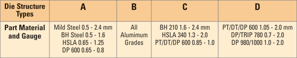 |
| Fig. 3—The Chrysler Die Engineering Standards Department has developed four types of die structures to guide engineers during die design, depending on part specifications, tooling force and material strength. Type A dies are the lowest cost, Type D the most robust, costly and time intensive for die construction. |
Type C and D die structures are the primary standards used at Chrysler for designing dies for AHSS, which are subjected to higher forces per unit area than are dies developed for traditional steel parts. Compared to more traditional dies, Type D structures feature:
• Increased rib thickness in all working areas;
• More robust guiding and healing standards, for thrust control;
• Inserts in all forming/flanging/ restrike conditions with smaller separate details to accommodate a nitride (with absence of white layer) plus physical vapor deposition (PVD) coating applied to all forming and flanging details. Trimming details are left uncoated based on research and production experience that found little tool-wear improvement.
• Stricter metallurgical quality standards for D2 and 4140 steels;
• Enhanced die-heattreatment methods and standards, local surface heattreat induction hardening for 4140 and furnace hardening and double pass tempering requirements for D2 steel inserts; and
• Simplified and robust maintenance procedures (welding and finishing requirements for physical vapor deposition coating application).
Die Materials, Heattreatment and Coating Standards
Chrysler has evolved to a simplified die-material usage strategy for AHSS, considering cost, die timing and ease of plant maintenance. We are using lower-grade irons (NAAMS G2500) for nonworking die elements and 4140 and D2 steel for inserts when required. Type C die structures use larger pearlitic nodular-iron castings in working areas, with 4140 inserts in local areas of high wear and for areas requiring die adjustment for quality.
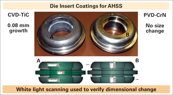 |
| Fig. 4—Chemical vapor deposition (CVD) and PVD coatings have been studied, and as depicted, PVD experiences no size change—the key reason for its use. |
D2 steel was chosen for AHSS Type D structure parts for all working surfaces, after considerable trials with some of the latest comparable grades. We found that conventional D2 performs well when following the proper metallurgical quality and strict heattreatment processes. This was proven to be true when nitriding (without white layer) plus application of a physical vapor deposition (PVD) coating. In addition, D2 offers the lowest overall cost and is most readily available globally.
Chemical vapor deposition (CVD) and PVD coatings have been studied, as applied research projects and in production trials. We have compared distortion experienced by tools undergoing each process (Fig. 4). As depicted, PVD experiences no size change, the key reason for its use.
Type D Draw Dies
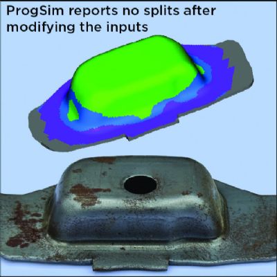
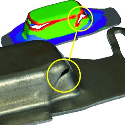
To process and design draw dies for AHSS parts, we account for three primary conditions: abnormal die deflection, increased tool wear and additional geometry to better control the higher degree of springback. To combat these conditions, a new and unique die-structure standard has been developed to incorporate increased rib thickness in working areas; use of separate details made from D2 steel; and special heeling to combat thrust. To derive this new structure, we employed standard use of finite-element topology and topography optimization (Fig. 5) to study key load paths in the die structure. We then sought to increase these critical sections to reduce deflection and prevent catastrophic failure.
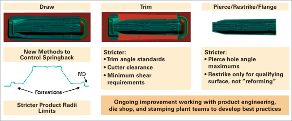
To control springback, die engineers work early with product-engineering teams to derive part geometry with even length of line, and follow product rules for critical forming radii. Use of formations such as stake beads induce an even strain distribution at die home position.
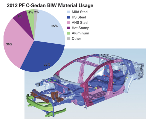
More than 80 percent of Chrysler’s AHSS parts are stamped in progressive dies—these are small underbody elements. However, we expect to produce a growing number of larger parts during the next 5 yr., requiring line-die processes.
Trim- and Flange-Die Design for AHSS
Since Chrysler die standards take into account overall tooling force, light-gauge DP600 parts fall into the same die-design category as do mild-steel parts. For example, the trim die for a DP600 (0.80 mm) front floor pan uses Type 4140 lower inserts, induction hardened at the trim working service. No additional coating is used. Using a breakage of 10 percent plus minimum sheetmetal thickness produced the highest-quality trim condition.
In another case, building a progressive die used to stamp parts from 1.6-mm DP980 steel, engineers paid close attention during the feasibility phase to gaining product geometry to support stamping production. Trimming elements are of furnace-hardened D2 tool steel, with a standard breakage of 10 percent plus sheetmetal thickness. No additional coating was applied, and we found that with good preventive maintenance, we can satisfy high-volume requirements (more than 400,000 parts/yr.).
Flanging operations, in most cases, produce the greatest local tool wear of all operations. Thus, we’ve mandated use of D2 inserts with nitride with the additional PVD coating application for all working areas. Since the high working forces are local in the flange areas, these structures were only locally increased; the remainder of the die structure in nonworking areas remain similar to the die standards used for mild-steel panels.
Pierce-Die Design
Over the past several programs, Chrysler’s pierce-die standards have evolved through a combination of production experience and applied research, through consortium project participation. Among the results:
• Conical-tip punches optimize longevity for Type D standard parts. Compared to traditional flat-profile punches, performance increased by as much as 40 percent (measuring quality by burr height).
• For all high-strength and AHSS steel parts thicker than 1.2 mm and with yield strength exceeding 250 MPa yield strength, a 10- to 15-percent clearance per side provides optimum results.
• Traditional M2 punches with A2 buttons—uncoated—are used. PVD-CrN coatings have been applied in production, with little benefit.
• To optimize piercing performance with high-strength steels, conical-tip punches, larger punch clearances and more stringent maintenance intervals (approximately every 100,000 hits) get the call.
• Lower value for maximum pierce angles allowed than for mild-steel parts.
Punches and buttons following these guidelines show little wear after 100,000 cycles, even for parts running DP980 material at 1.6 mm. MF Industry-Related Terms: Nitriding,
Piercing,
Stripping,
Surface,
Tempering,
Thickness,
Forming,
Induction Hardening,
Burr,
Case,
Die,
Draw,
FlangeView Glossary of Metalforming Terms Technologies: Materials, Software


 Webinar