Peter Ulintz
Punch-Tip Pressures
August 1, 2010Comments
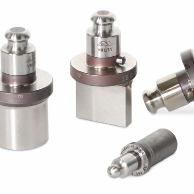
Question: We have several dies that experience chronic punch-tip breakage. I’m not sure if the punches were designed/selected properly for our particular application, other than the point diameter matches the hole size specified on the part drawing.
I know how to calculate the force to punch the hole, but how do I know if that force will exceed the limits of the punch tip? Is there some sort of chart available?
Answer: I suggest you contact your punch manufacturer for help. There are many variables that can influence punch-tip breakage and your punch manufacturer will be a valuable resource for quickly finding the root cause of your failure(s).
Still, it is important to understand the science behind the problems we experience in the press shop. Therefore, we’ll discuss the calculations you inquired about and how you can use these results as selection criteria for your punches.
Calculating punching force and punch-tip pressure is fairly straight forward. The generally accepted method for calculating the force required to create a punched hole is: Punch force (Fp) is the product of the punch tip profile length (L) times sheet material thickness (t) times the sheet material shear strength (st).
Fp = (L) (t) (st)
 |
The punch tip profile length (L) for a round punch is found by multiplying the point diameter (d) times pi (p).
L = pd
The punch tip profile length (L) for a nonround shape is the linear distance around the punch point.
Obtaining accurate shear stress data (st) can be quite difficult. As a result, approximations are commonly used. The approximate shear strength for mild steel is 70 to 80 percent of the ultimate tensile strength of the steel.
Shear strength will vary among different alloys but also can vary significantly within the same material type. Shear strengths for copper, for example, have been reported to be between 50 and 90 percent of their ultimate tensile strength, depending on the alloy.
Regardless of material type or alloy, if dull edges and large cutting clearances are used in the die, the shear strength begins to approach the nominal tensile strength of the material because the fracture mode becomes closer to pure tension rather than pure shear. For this reason, many tooling engineers will play it safe by using nominal tensile strength values in their calculations. However, this may be a costly safety net since the final punch often will be over-designed.
After calculating the punching force (Fp), determine the tip pressure (Ft). For standard shoulder punches, tip pressure will equal the punching force divided by the cross-sectional area (A) of the punch tip.
Ft = Fp/p (1/2d)
 |
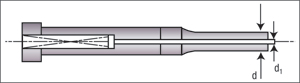
If the punch has a spring elector pin, the cross-sectional area is reduced by the area of the hole in the punch face. The force on an ejector type punch, similar to that shown, is found by:
Ft = Fp/p (1/2d – 1/2d1)2
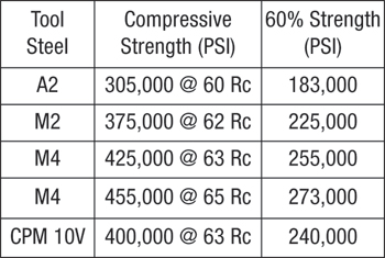
Punch tip performance is reported to be best when the maximum loads remain below 60 percent of the compressive strength of the punch body material. The table below contains compressive strength data for some common tool steels and heat treatments. To minimize punch-tip breakage problems, the punch tip (Ft) load should be less than the value shown in the 60 percent strength column.
Taking this engineering approach to punch selection eliminates guesswork and maximizes punch-tip strength economically.
MF
View Glossary of Metalforming Terms
Technologies: CNC Punching, Tooling