


Control of slide velocity during the working portion of the stroke reduces punch impact forces by reducing impact loading as punches contact the workpiece material. When punches first contact material, the press begins to generate tonnage as the material enters its plastic range. A higher slide velocity at the impact point reduces the amount of time in which this occurs. As a result, the amount of force required to overcome material shear strength actually increases toward the ultimate tensile strength, increasing the tonnage required to make the part. So, reducing slide velocity has the opposite effect by allowing more time for blanking or forming to occur and the material to shear at its specified load.
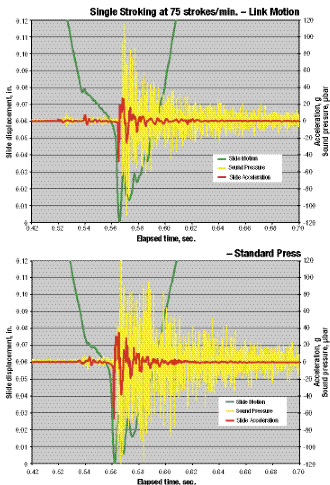 |
| Fig. 2—These graphs track sound pressure, slide motion and acceleration for 80-ton presses blanking at 75 strokes/min. Note the reduction in sound with a link-motion press (top) as compared to a standard crank-motion press (bottom). |
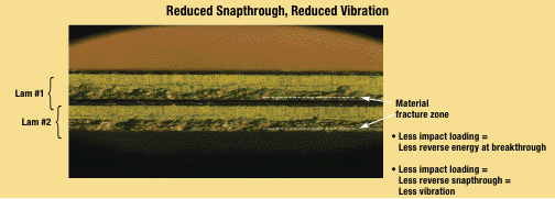
Reducing impact velocity, as stated earlier, also will reduce the negative effects of snapthrough and subsequent vibration. In blanking or piercing, when material fractures and the punch breaks through, energy almost instantaneously releases into the part, tooling and press. This can lead to premature punch failure and press damage. Broken bolts, cracked guards and similar damage indicate excessive vibration, and any efforts to reduce snapthrough and vibration, including reducing slide velocity, will have positive results (see Fig. 1). In addition, reducing slide velocity at the point where stripper plates or draw rings contact the workpiece material minimizes bouncing and produces more consistent forming results.
Drawing, Embossing and Other Operations
On drawn parts, reducing slide velocity provides more time for the material to flow. If slide velocity exceeds the draw rate of the material, the part can become excessively thin, or can tear. This problem is exacerbated on deeper draws, since slide velocity increases as the stroke moves farther from bottom.
Additional forming operations such as embossing, coining or difficult bendingcan benefit from either a slower flow rate or the ability to hold material so that it can take a set. This helps hold tighter tolerances, reduces springback and produces higher-quality parts in fewer die stations.
More time spent in the working part of the stroke may allow more time for in-die welding, tapping and other operations, resulting in fewer secondary operations.
Reducing slide velocity also reduces the frictional forces encountered during forming. This in turn reduces the heat generated and allows the die to run cooler, which improves tool life.
Finally, noise reduction also is a benefit of reducing slide velocity. Fig. 2 compares noise levels during blanking on two 80-ton presses, one with standard crank motion and one with link motion.
Timing Issues Pose Challenges
For all of the advantages of controlling or reducing slide velocity during the working part of the stroke, definite disadvantages exist. The simplest to reduce slide velocity is to slow down the press, and this obviously reduces output.
Procedures do exist to allow stampers to reduce slide velocity and still maintain or even increase production rates, but these practices pose unique challenges. When reducing slide velocity during the working portion of the stroke, time lost can be regained during the nonworking portion of the stroke. However, this reduces the amount of time available for other actions, such as coil or blank feeding, or part transfer, to occur. Also, lost time available during each stroke can limit available stopping time and negatively affect die-protection systems.
Depending on the application, a net production loss may be realized if the time needed for these other actions dictate a slower running speed. Considering that the goal usually is to produce parts at the maximum rate, reducing slide velocity during the working part of the stroke may be counter-productive.
Reducing time during the nonworking portion of the stroke translates into increased slide velocity. While this may not appear to be significant, the increased velocity can result in increased impact and vibration at the point of stripper-plate lift off. In a typical die arrangement with a spring-loaded upper stripper plate, the upper stripper remains stationary while it contacts the lower die. As the slide accelerates on the upstroke, it lifts the stripper off of the lower die. This action immediately accelerates the stripper from zero to the slide velocity at the point of pick up. An excessively high slide velocity can cause stripper-bolt failure or excessive vibration.
In the end, controlling slide velocity has many potential benefits. However, as with any production system, it is only one of many factors to consider in meeting the goals of quality, productivity and reliability. MF
View Glossary of Metalforming Terms
See also: Nidec Press & Automation
Technologies: Stamping Presses


 Video
Video